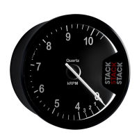
Installation ST500 Tach-Timer
© Stack Limited
10
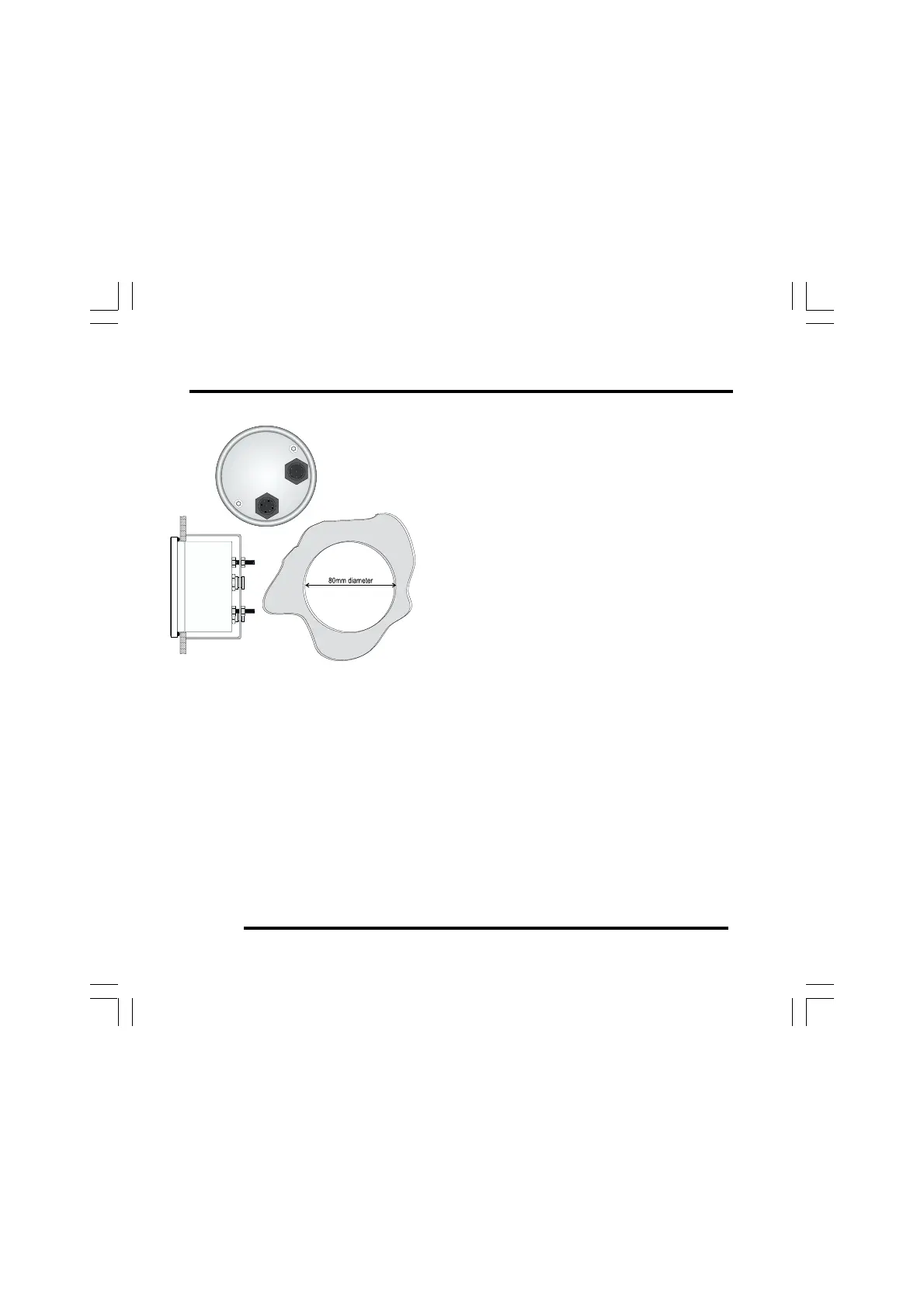
Figure 4 - Rear view and mounting
arrangements
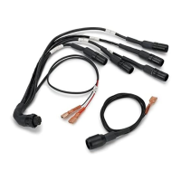
3 Note that your installation may not use all
the cables in the harness. You should tie
back and protect all unused connectors.
4 Begin at the instrument panel where you
will install the Tach–Timer. Lay the wiring
harness into the vehicle, with the cable
branches running to their appropriate lo-
cations in the vehicle. Allow sufficient slack
in the harness so that you can connect it to
the Tach–Timer before you insert the dis-
play into the instrument panel.
5 You should route all cables to be no closer
than 75 mm (3 inches) to the ignition HT
leads or the distributor cap. Do not run ca-
bles close to sources of intense heat.
6 Fit cable glands to protect the cables where they pass through bulk-
heads or panels. This is particularly important when you pass cables
through carbon fibre partitions, which can wear through them very
easily.
Tach–Timer Display
1 Connect the wiring harness to the Tach–Timer. There are two con-
nection ports on the back of the display, but you can insert the 8-way
connector only into one of them. Do not try to force the connector