ST500 Tach-Timer Installation
© Stack Limited
21
1 Drill a hole or install a bracket to support the external light in the
location you have selected.
2 Connect the light to the 6-way connector on the Tach–Timer.
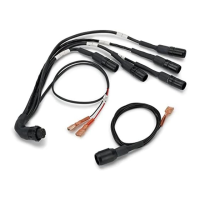
Battery connection
The Tach–Timer accepts power from the vehicle electrical system through
the two cables labelled ‘B+’ and ‘B–’ in the wiring harness.
1 Connect the black ‘B–’ cable from the harness directly to the battery
negative terminal.
2 Connect the red ‘B+’ cable of the harness to a fused supply from the
battery positive terminal. The fuse rating for this line should be no
higher than one amp. This line should become ‘live’ only when you
switch on the vehicle ignition.