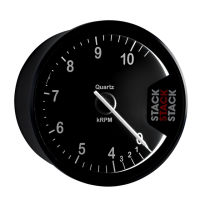
Installation ST500 Tach-Timer
© Stack Limited
12
1 Drill holes or install brackets to support the controls in the locations
you have selected for them.
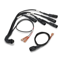
2 Connect the correct cables of the harness to each control.
Engine Speed Measurement
This connection is dependent on your ignition system. You should read these
instructions carefully and make certain you have identified the correct connec-
tion point before you begin.
To measure engine speed you must make the correct connections between
the Tach–Timer and the vehicle ignition system. Contact Stack for advice
if you have a complicated ignition system.
Ignition System Connection point (Orange wire)
Coil and Points Coil negative (Low tension)
HEI Systems Coil negative (Low tension)
Magneto (external or internal) Ground switch terminal (magneto side)
MSD Tachometer output
Magneto CD (2-stroke) Use HT pick up (ST697)
Table 1 – Connection to the ignition system
The following drawings show ignition systems in detail:
Standard contact breaker system
Connect the ‘ES’ wire of the harness to the negative ‘CB’ terminal on the
coil as shown in Figure 5.