Installation ST500 Tach-Timer
© Stack Limited
18
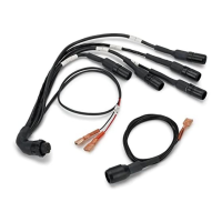
the LAP input as shown in Figure 3. To fit the manual lap timing option
you will require the switch (ST517) and the wiring harness (ST918037).
With the manual lap timing option fitted, the driver must press the Lap
Timer button as the vehicle crosses the start line.
Because manual lap timing requires a positive action from the driver, it
is less accurate than the automatic lap timing option by IR sensor al-
ready described. Furthermore, because split timing also comes directly
from the lap timing input, any errors in the lap timing will degrade the
accuracy of split times. For these reasons, Stack does not recommend the
use of manual lap timing.
Wheel Speed Sensor (optional)
The Stack ST670 wheel speed sensor generates an electrical pulse for the
Tach–Timer whenever a ferrous target, such as a wheel bolt, passes close
to its end. You must install the sensor so that it detects the wheel turning
by a sequence of such targets.
Once you have installed the wheel speed sensor successfully, the Tach–
Timer uses the pulses to measure the vehicle speed. You must set-up the
Tach–Timer to use this information.
1 Select a suitable and convenient location for the sensor. For each wheel
rotation, the sensor must detect at least one ferrous target (for
example, a wheel bolt). Note that the sensor will not ‘see’ items such
as alloy wheel spokes or other non-ferrous objects and you should