ST500 Tach-Timer Installation
© Stack Limited
19
not try to use these as targets.
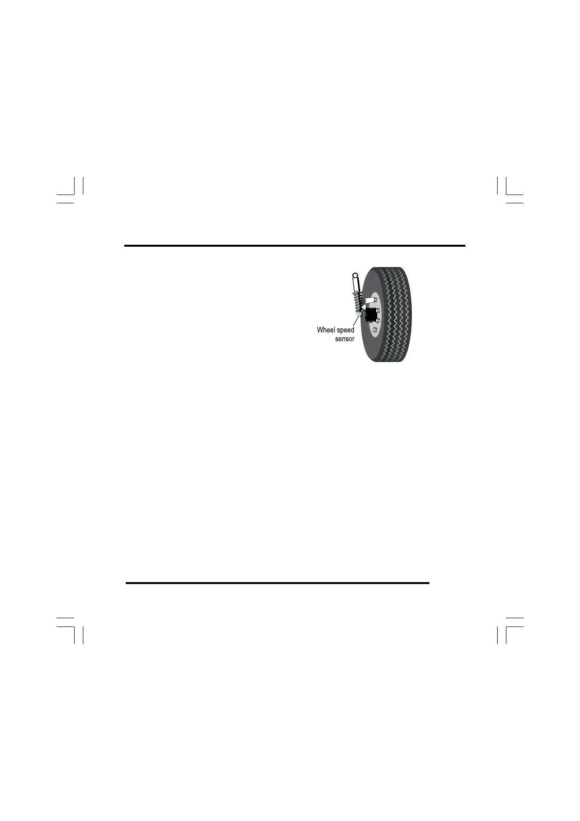
• If possible, choose a wheel that ex-
periences negligible wheel spin, lift
or lock-up – for example, an
undriven wheel.
• Ideally, the targets should be
equally spaced around the wheel
so that, with a constant wheel
speed, the electrical pulses occur at
regular intervals.
• To avoid excessive heating do not install the sensor too close to
the brake disc.
• Position the sensor no closer than 75 mm (3 inches) to ignition
HT leads or sources of intense heat.
2 Make a suitable rigid bracket to support the sensor and attach it to
the vehicle. Fit the sensor to the bracket. Do not over tighten the
sensor.
3 Adjust the clearance between the end of the sensor and the ferrous
targets so that the gap is nominally 1.0 mm ± 0.5 mm (0.040 ±0.020
inches). Make certain there are no other objects passing within 4 mm
(X-inch) of the sensor when the wheel rotates.
4 Attach the wire labelled ‘WS’ of the harness to the sensor at the 4-
Figure 9 - Wheel speed sensor