ST500 Tach-Timer Installation
© Stack Limited
15
period after it senses the first beacon. This ‘lap masking’ feature
prevents multiple triggering within each lap.
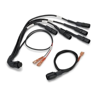
2 Attach the wire labelled ‘LAP’ of the harness to the sensor at the 4-
way ‘Sure-Seal’ connector. Take care to assemble this connector in
the correct orientation. Press the two halves of the connector fully
together to ensure a good waterproof seal.
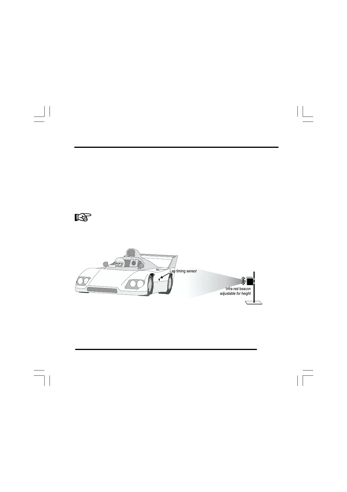
Use a rigid mounting bracket to attach the sensor to the outside of the vehicle
where it can detect the signals from the trackside beacon. Use the two M18 ×
1 mm threaded nuts supplied to secure the sensor.
Figure 8 - Infra-red beacon alignment