calculate the number of steps per revolution, knowing that one revolution consists of 360 degrees.
Make sure that movement to the right from the main window of XiLab corresponds to the movement to the right of the stage. If
not, then check the box Reverse field Stepper motor -> Motor parameters .
Hardware limit switches setting. Homing.
Note. This section describes the using of motorized stages with hardware limit switches. If your system is not
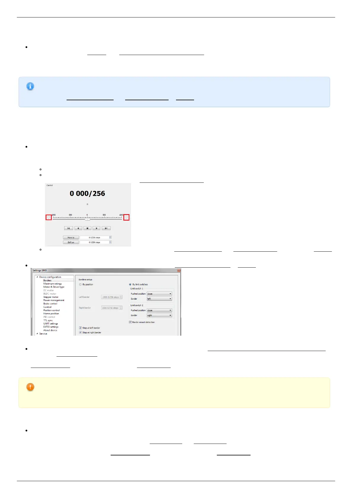
provided with hardware limit switches, it is recommended to disable stop by limit switches in settings. To do this,
unmark Stop at right border and Stop at left border in Borders tab.
There are positioners with limited (translators) and an unlimited range of motion (rotators). The limitation of movement range can be
done by position or with limit switches using. When you work with translators if its limit switches are configured incorrectly there exists
a risk to break down mechanics, since moving part can try to go out of motion range. Rotators do not have such problem. Moreover, it
should be kept in mind that rotator may have only one limit switch.
To work with limit switches you must specify which one will be left and right. Sometimes it is unknown in advance and we only
know that both switches are connected and fire if the corresponding limit of the motion range is reached. The stage jam is
possible if the limit switches are configured improperly. Therefore, the controller supports just a simple detection of incorrectly
configured limit switches, shutting down the movement on both of them. Please make sure that:
The stage is far from limit switches;
Switches polarity is configured correctly (limit switches indicators are off in the main window of XiLab). In the case of
incorrect settings, change their polarity (Borders -> Pushed position), indicators should go out.
Shutdown mode is activated on both of limit switches ( Stop at right border and Stop at left border are marked in Borders
tab).
Mark the flag detecting improper connection of limit switches Border misset detection in Borders tab.
Tab with limit switches settings
Controller can switch to Alarm state after false limit switch response, if Enter Alarm state when edge misset is detected is
enabled in Maximum ratings tab. It is recommended to enable it. Start the movement in any direction from the main window of
XiLab up to Alarm state or stopping by the limit switch. When an Alarm occurs you need to reverse limit switches by changing
Borders->Border with reversed values in the Stepper motor tab.
Warning. The protection against mistaken limit switches connection doesn't guarantee the complete solution of the
problem, it only makes the initial configuration procedure easier. Don't start the movement with mixed up limit
switches if any of them is active, even if the protection is on.
There are still two ways to determine which of the limit switch is right and which is the left:
You need to know how each of the limit switches is connected to the positioner. When loading a profile with the default settings,
switch connected to pin 9 of the D-SUB connector is considered as left, while switch connected to pin 8 - as right. Their location
relative to the positioner is configured in the fields Limit switch 1 and Limit switch 2 (see screenshot above). Start the system at
the low speed (<100 ш/с) when it is far away from limit switches. If the direction of movement to the switch in a real setting
differs from the expected, change Borders->Border values with reversed in the Stepper motor tab.