If it is possible to get limit switches activate them and note the correspondence between indicators in XiLab and each particular
switch. Then start the system at the low speed (<100 ш/с) when it is far away from limit switches and make sure that the
system moves to the right switch. Compare this to what you see in the main window of XiLab. If the direction of movement to
the switch in a real setting and in the main window differs, change Borders->Border values with reversed in the Stepper motor
tab.
For detailed information refer to motion range and limit switches.
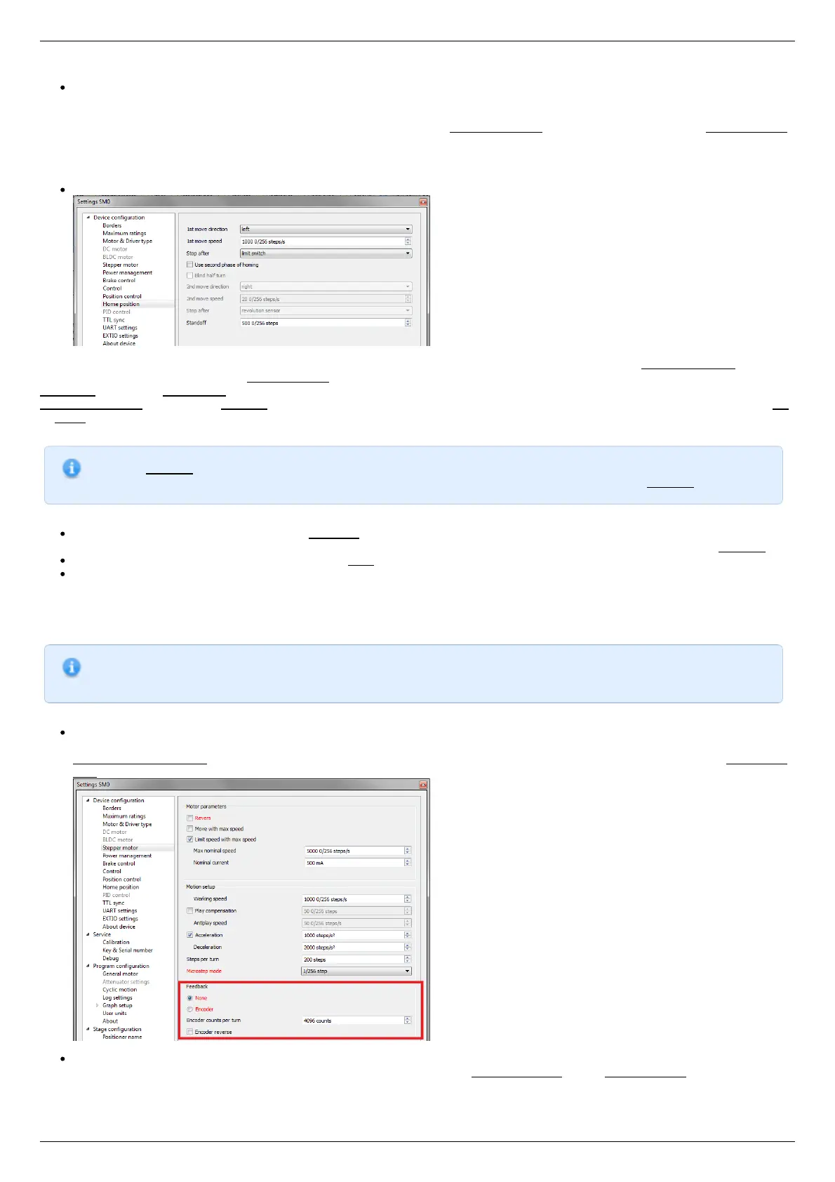
Controller has a useful function called automatic Home position calibration to set the initial position of the motorized stage.
We will consider the most simple configurations with a single phase only. Start from the setting of the 1st phase speed which is
approximately 5-10 times lower than Working speed. It is necessary for higher precision of automatic calibration procedure. In the filed
Stop after specify the limit switch to make the stage reached one of the limit switches during the calibration (direction is selected in the
1st move direction). In the field Standoff specify number in steps, for which stage must be driven away from the limit switch. Click Ok
or Apply.
Note. Standoff value is signed. Positive direction is right. That is, if the auto-calibration procedure is set up on the
right limit switch, then in order to move stage away to the left you should type negative value in Standoff field.
Start the automatic calibration by clicking Go home in the main window of XiLab. The result of it is a movement of the positioner
to the specified limit switch with a relatively low speed and the shift away from him to the value specified in the field Standoff.
After completion of the calibration process, press Zero in XiLab to set the origin of coordinate system for your stage.
Repeat the calibration process again. The stage must return to the zero position. Please pay attention that there can be slight
deviations from zero connected with calibration procedure error.
Encoder parameters setting
Note. This section describes the using of motor with encoder. If you motor without an encoder, the parameters
described below can be left unchanged.
Any encoder has Pulse Per Turn - PPT parameter (sometimes it is called PPR - Pulse Per Rotation). For correct operation of
the encoder with controller you should enter the number of encoder counts per revolution, which is equal to 4xPPT in the
Encoder counts per turn field in XiLab. For example, if your encoder has 1024 pulses per turn, specify 4096 in the Counts per
turn:
Start the motor rotation from the main window of XiLab. If everything is configured correctly, the green indicator ENCD will light
in the bottom of window. If ENCD has yellow color, you should mark Encoder reverse in the Stepper motor tab. Red color of
EDCN points to the problem with encoder position recalculation..