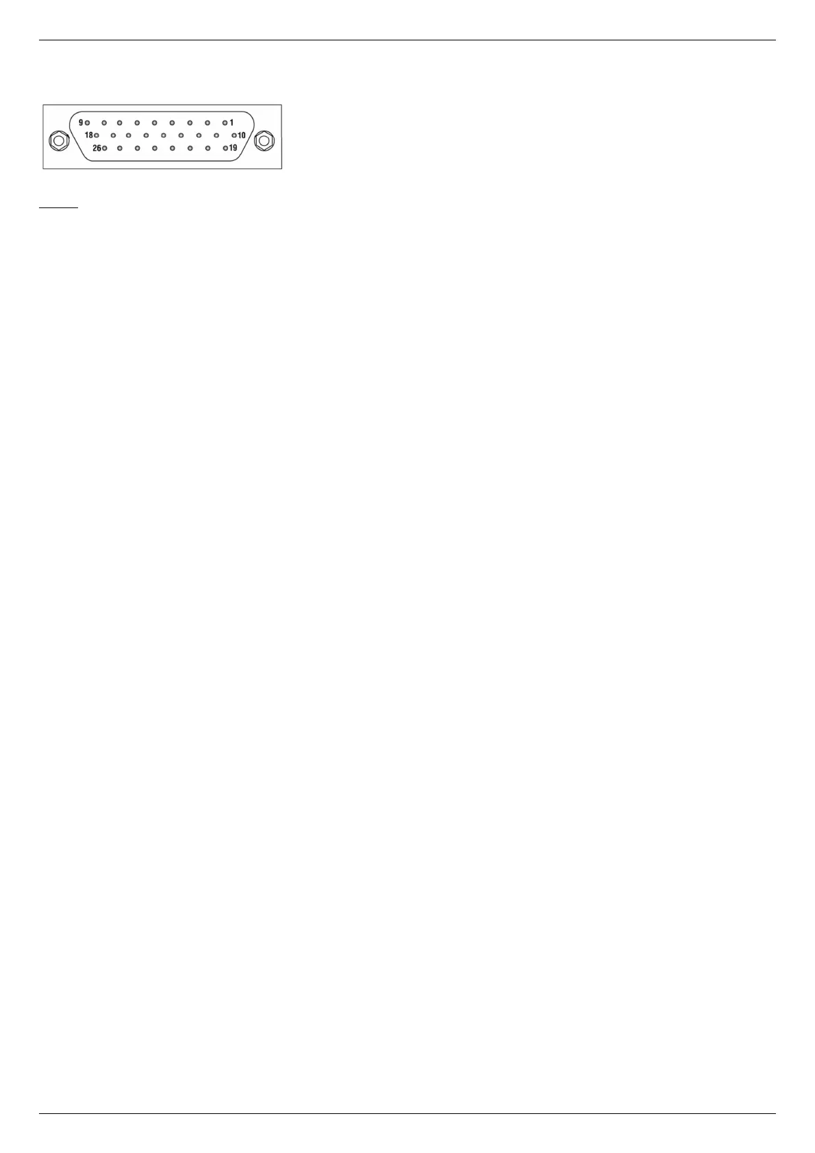
One-axis controller model contains a HDB-26 female DSub connector.
Pinout of the supplementary HDB-26 connector, front view.
Pinout:
1 - NC, not used.
2 - NC, not used.
3 - NC, not used.
4 - GND, ground.
5 - NC, not used.
6 - Synchronization input.
7 - Synchronization output.
8 - RX_1, serial port input.
9 - NC, not used.
10 - NC, not used.
11 - NC, not used
12 - NC, not used.
13 - DIR_1, Direction signal for the external driver.
14 - GND, ground.
15 - +5V.
16 - BRAKE_1, brake control output.
17 - CLK_1, Clock signal for the external driver.
18 - TX_1, serial port output.
19 - NC, not used
20 - NC, not used
21 - NC, not used.
22 - GND, ground.
23 - PBRK_1, Magnetic brake output.
24 - +5V.
25 - IO_1, input-output pin.
26 - POT_1, analog input.