4.1.3. Two axes system
Enclosure view
Two-axis controller model consists of two controller boards in a metal case. Case dimensions are 122 x 45 x 106 mm.
Front panel contains power supply connector, USB-B data connector, supplementary two-axis system connector , USB cascade
connector, and power LED. The cascade USB-A output connector is used to connect several two-axis cases in line terminated with
either one-axis or two-axis case. This way a required number of axes can be connected to the computer with a single USB cable. The
front panel also contains status LED, left and right limit switch LED, left and right movement buttons for each of the two controller
boards of the two-axis system.
Rear panel contains positioner connector for each of the two controller boards, a joystick connector.
Connectors
Positioner connector
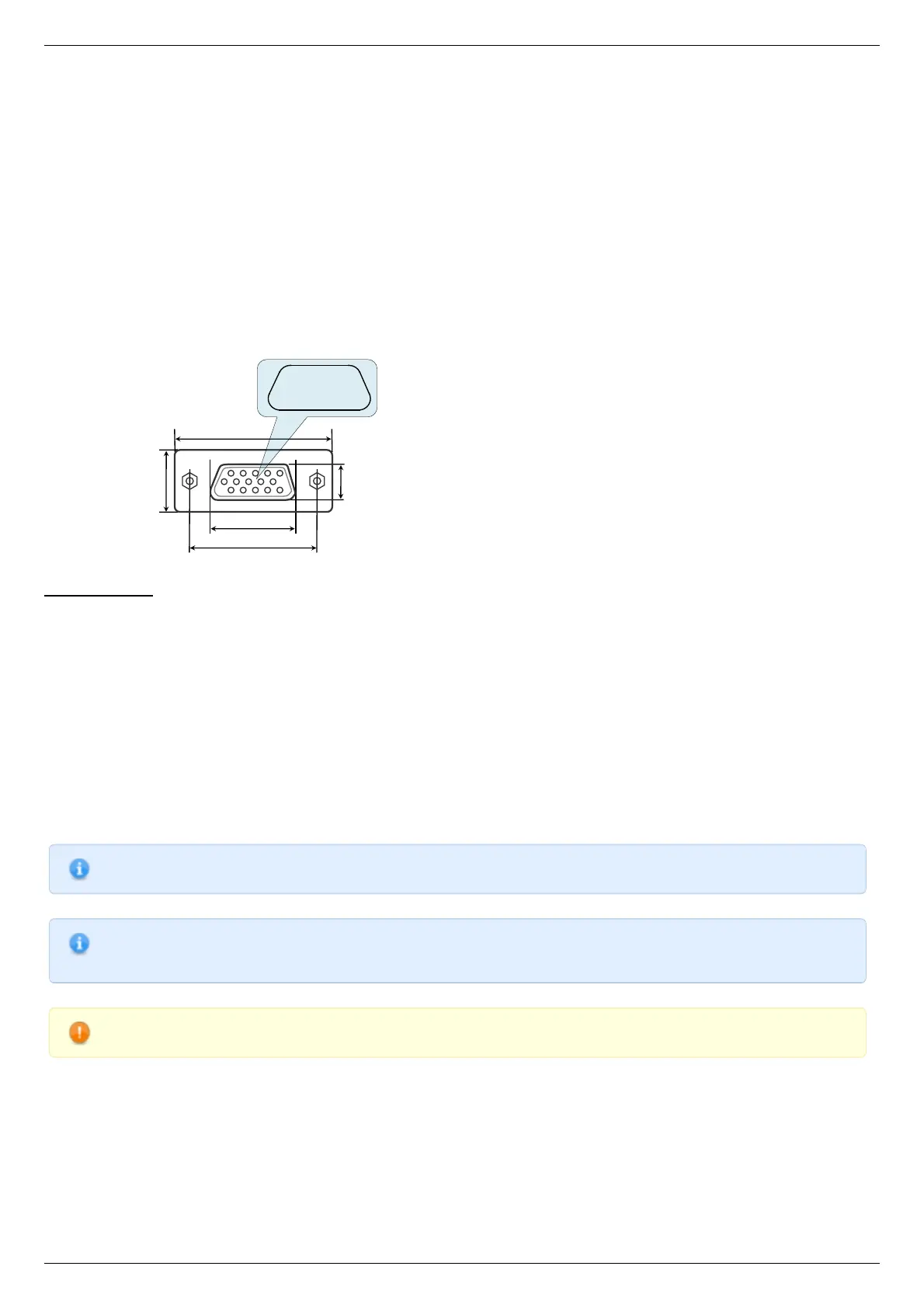
A female DSub 15-pin connector for positioner is mounted on the controller board.
Dimensions and numbers of the pins in DSub connector (front view).
Pins functionality:
1 - Not phase B of SM or - DC of the motor
2 - Phase B of SM or + DC of the motor or phase B on BLDC motor
3 - Not phase A of SM or - DC of the motor or phase C on BLDC motor
4 - Phase A of SM or + DC of the motor or phase A on BLDC motor
5 - 500mA - for 8SMC5, stabilized output for encoder power supply
6 - One-wire interface for positioner identification (for Standa hardware only)
7 - Logic ground for limit switches, encoder, etc.
8 - 2nd limit switch
9 - 1st limit switch
10 - Encoder channel A
11 - Encoder channel B
12 - Revolution sensor input
13 - Inverted Encoder channel A
14 - Inverted Encoder channel B
15 - Inverted revolution sensor input
Note. Only firmwares 4.1.0 and older support BLDC
Note. Outputs 1 & 3 and 2 & 4 must be connected together for proper DC motor function if the nominal current of the
motor is higher than 3A.
Warning. Plugging in/out the motor to the controller is not recommended while motor windings are under voltage.
Power supply connector. 1 and 2 axes system