4.5.7. General purpose digital input-output
Output is located on BPC connector. It allows user to configure it as input or output. Logical level one is considered to be active.
However it can be inverted so that logical level zero is considered active.
Type TTL
Logic zero level 0 V
Logic one level 3.3 V
Table 4.5.4.1 - Input parameters
In input mode you can get information about logical level on input (see Controller status), or initiate the following actions during
transfer to active state (or during transfer to non-active state if the input is inverted):
Perform STOP command (quick stop).
Perform PWOF command (windings power supply switch off).
Perform MOVR command (shift to the given distance with last used settings).
Perform HOME command (automatic position calibration).
Enter Alarm state (turn off H-bridges and wait reinitialization).
It does not matter how the state of the input becomes active (after changing the invert states, or when changing the voltage level).
The controller uses a software debounce the input. Initiating the action takes place only when the active state of the input buttons
lasted for more than 3 ms.
WARNING. When you turn on or reboot the controller at the input voltage level of the input is present, which is
considered to be active, the controller interprets it as a signal to trigger any of the actions.
Note. Digital input has weak pull down to the ground.
In output mode it is possible to set active or inactive logic level on the following events:
EXTIO_SETUP_MODE_OUT_MOVING – Active state during motor movement.
EXTIO_SETUP_MODE_OUT_ALARM – Active state when controller is in Alarm state.
EXTIO_SETUP_MODE_OUT_MOTOR_ON – Active state while power is supplied to the motor windings.
EXTIO_SETUP_MODE_OUT_MOTOR_FOUND – Active state while motor is connected.
Logic type
TTL 3.3
V
Update frequency 1 kHz
Nominal current 5 mA
Table 4.5.7.2 - Output technical characteristic
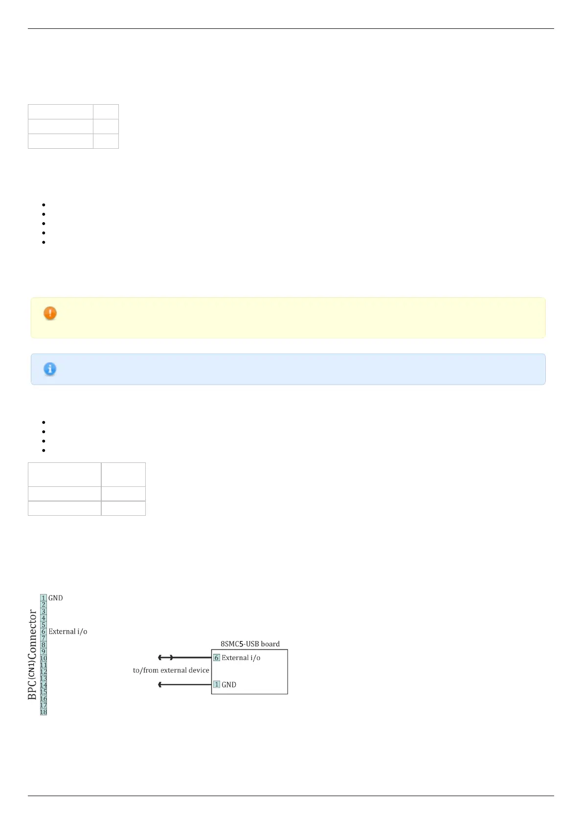
Connection diagram
Controller board
Digital output is located on the BPC connector
Scheme of connection to digital input/output for the controller board
One-axis and two-axis systems