Helios Users Guide
www.starcomgpsglobal.com 154
Installation
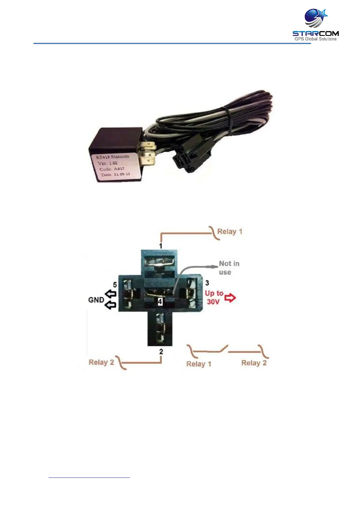
The following image shows the relay and socket with cables.
The following diagram illustrates the relay cables connection.
1. Relay connection 1
2. Relay connection 2
3. Main power 12 V (+) (usually RED)
4. Data (GRAY) – NOT IN USE
5. GND x 2 (-) (usually BLACK)