BR 80040
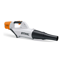
N Fit the diagnostic socket (12).
N Insert and tighten down the screw (11).
N Fit the cable lug (8).
N Insert and tighten down the screw (7).
N Fit flag connector (9) on ignition module’s contact.
N Push the black and yellow wires of wiring harness (6)
into the guides (arrows).
N Fit the wiring harness (6) in the guides (arrows).
N Fit the ignition lead (14) in the guides (arrows).
N Fit the spark plug boot.
N Install the shroud, @ 7.5.
N Install the rewind starter, @ 6.14.
N Fit the filter cover, @ 7.3.
14.4 Removing the Impulse Hose
N Preparations, @ 3.1.
N Remove the airflow shroud, @ 14.2.
N Pull off the impulse hose (5).
14.5 Installing the Impulse Hose
N Coat opening in impulse hose (5) with press fluid.
N Push the impulse hose (5) onto stub on carburetor (7)
as far as stop.
N Install the airflow shroud, @ 14.3.
14.6 Removing the Manifold
N Preparations, @ 3.1.
N Remove the airflow shroud, @ 14.2.
N Remove filter housing and carburetor, @ 8.2.
N Tighten down the screw in the hose clamp (4).
N Remove the manifold (3) with hose clamp (4) and
flange (2).
N Pull the sleeve (1) out of the manifold (3).
N Pull manifold (3) out of the flange (2).
N Remove the hose clamp (4) from the manifold (3).
14.7 Installing the Manifold
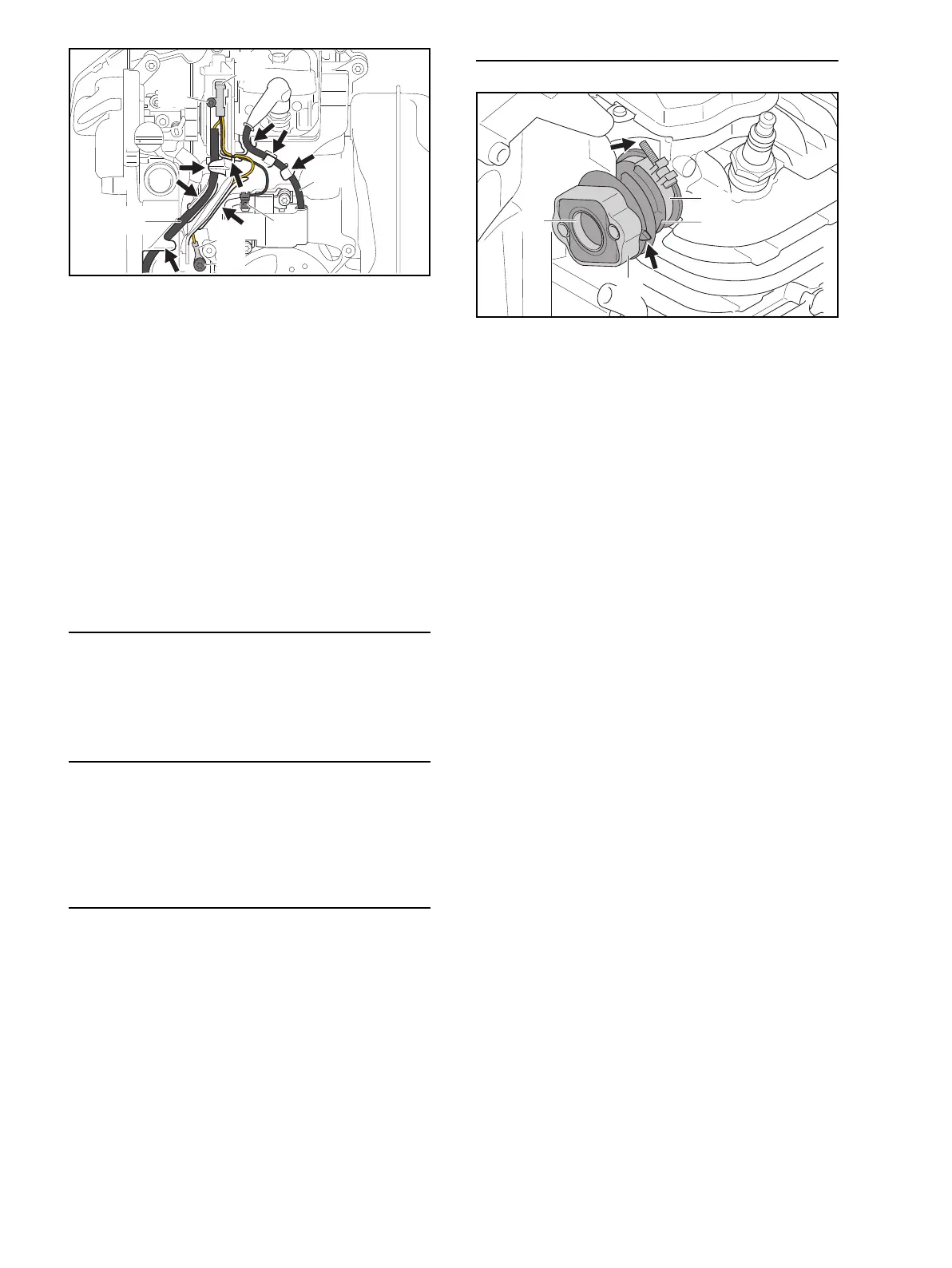
N Fit the hose clamp (4) on the manifold (3) with the
screw facing forwards.
N Push the flange (2) onto the manifold (3).
N Fit the sleeve (1) in the manifold (3).
N Coat inside of manifold (3) in area of hose clamp with
press fluid.
N Push manifold (3) with hose clamp (4) and flange (2)
onto the intake stub as far as stop so that the arrow-
shaped tab (arrow) faces forwards.
N Tighten down screw on hose clamp (4) as far as stop,
makig sure its end (arrow) does not knock against the
cylinder.
N Install the filter housing and carburetor, @ 8.3.
N Install the airflow shroud, @ 14.3.
14
9
8
7
6
11
12
0000-GXX-6661-A0
2
3
1
4
0000-GXX-6662-A0

 Loading...