BR 800 45
17.1 Tools, Servicing Aids
– Socket, T20x125 – 0812 542 2041 or equivalent
– Socket, T27x125 – 0812 542 2104 or equivalent
– Locking screw – 4282 890 2700
– Screwdriver, T20 – 5910 890 2301 or equivalent
– Torque wrench – 5910 890 0302 or equivalent
– Torque wrench – 5910 890 0312 or equivalent
– Punch-down tool – 5910 890 4000
– Screwdriver, T27x200 – 5910 890 2415 or equivalent
– Socket, 18 mm
– STIHL OH 723 press fluid – 0781 957 9000
17.2 Removing the Stop Buffer
N Preparations, @ 3.1.
N Remove the backplate, @ 10.9.
N Use the punch-down tool 5910 890 4000 to push the
stop buffer (9) out of the inner blower housing (6).
17.3 Installing the Stop Buffer
N Coat cone of stop buffer (9) with press fluid.
N Press the stop buffer (9) into the opening in the
blower housing (6).
N Install the backplate, @ 10.12.
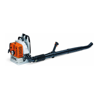
17.4 Removing Outer Blower Housing and Elbow
N Preparations, @ 3.1.
N Remove the backplate, @ 10.9.
N Take out the screws (7) and (10).
N Remove outer blower housing (1).
N Remove the elbow (12) with pleated hose, blower
tube and control handle.
N If necessary: Remove the O-ring (11).
N If necessary: Remove the control handle, @ 15.2.
N If necessary: Remove the pleated hose together with
the blower tube.
N If necessary: Remove the antivibration elements, @
11.2.
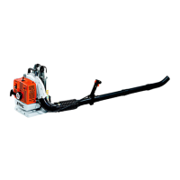
17.5 Removing the Blower Wheel
N Remove outer blower housing (1), @ 17.4.
N Remove the spark plug.
N Fit the locking screw 4282 890 2700 in the spark plug
hole.
N Use 18 mm socket to unscrew the hex nut (2).
N Remove the blower wheel (3).
17 Blower Assembly
8
6
1
3
11
12
5
7 P5x18
(4 Nm /
71 lbf. in.)
(12 Nm / 106 lbf. in.) D6x28 4
(30 Nm / 22 lbf. in.) M12x1.25 2
10 P5x18
(1.5 Nm /
13 lbf. in.)
9
0000-GXX-6680-A0

 Loading...