BR 800 47
18.1 Tools, Servicing Aids
– Socket, T27x125 – 0812 542 2104 or equivalent
– Locking screw – 4282 890 2700
– Torque wrench – 5910 890 0302 or equivalent
– Screwdriver, T27x200 – 5910 890 2415 or equivalent
– Screwdriver, 8x200 – 5910 890 2420 or equivalent
– Hook – 5910 890 2800
– Flat nose side cutting pliers
– HT red silicone sealant – 0783 830 2000
– Solvent-based degreasant containing no chlorinated
or halogenated hydrocarbons
– Two-stroke engine oil
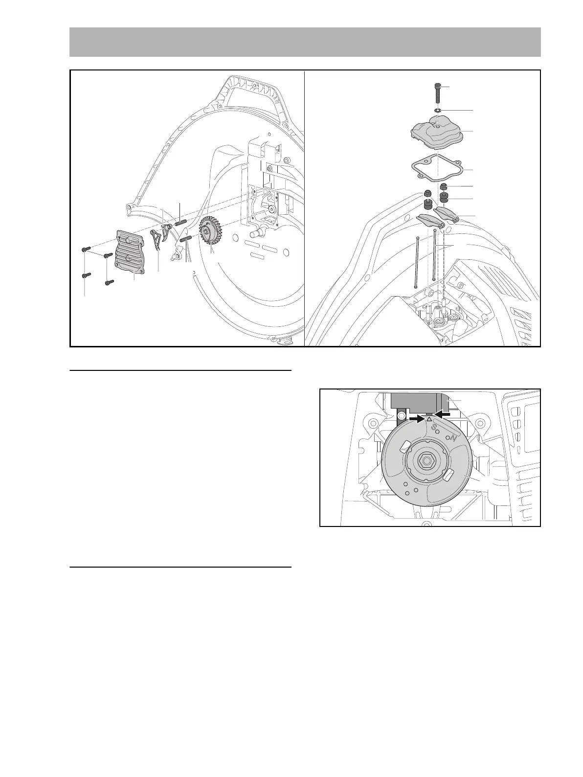
18.2 Removing Rocker Arms and Pushrods
N Preparations, @ 3.1.
N Remove the cover, @ 7.4.
N Remove the spark plug.
N Remove the rewind starter, @ 6.2.
NOTICE
The crankshaft must be set to top dead center on ignition
stroke to ensure correct installation of the cam gear (7).
Top dead center on ignition stroke can be set only with the
valve gear installed.
Set the crankshaft to top dead center on ignition stroke
before removing the valve gear.
Make sure that the position of the crankshaft is not
changed between removing and installing the valve gear.
N Rotate the flywheel (16) so that the mark (arrow)
points to the center of the short arm (arrow) of the
ignition module (17) and the rocker arms (9) do not
move in the process.
N If the rocker arms (9) move when the flywheel (16) is
rotated: Turn the flywheel (16) one more revolution.
N Take out the screw (15).
N Remove the sealing ring (14).
N Remove the valve cover (13).
N Remove the gasket (12).
N Unscrew the locknuts (11).
N Remove the sleeves (10).
N Remove the rocker arms (9).
N Pull out the pushrods (8).
18 Valve Gear
15 M5x30 (6 Nm /
53 lbf. in.)
11 M5
14
13
12
10
9
8
7
5
4
6
3
2
1 D4x16 (4 Nm /
71 lbf. in.)
0000-GXX-6007-A0
16
17
0000-GXX-6684-A0

 Loading...