BR 80042
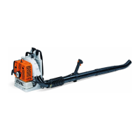
N Position the throttle cable (12) in the guides (arrows)
in the handle molding (2) and check the following
points:
– Installed position of throttle cable (12):
1. Black wire
2. Yellow wire
3. Bowden cable
N Lubricate web (19) in handle molding (2) with STIHL
multipurpose grease 0781 120 1110.
N Push blade receptacle of black wire onto the contact
spring (11) so that its closed side faces the contact
spring (11).
N Push the black wire with contact spring (11) into the
guides (arrows) in the handle molding (2).
N Push flag terminal of yellow wire onto the pivot (20) so
that its closed side faces the contact spring (11).
N Push yellow wire (11) into guides (arrows) in the
handle molding (2).
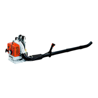
N Fit the setscrew (5) in the throttle lever (4).
N Lubricate opening (21) in lever (9) with STIHL
multipurpose grease 0781 120 1110.
N Fit the lever (9) in the throttle lever (4).
N Attach nipple of throttle cable (12) to hole (21) in lever
(9).
N Place the throttle lever (4) with lever (9) in the handle
molding (2).
N Fit the torsion spring (6) on the pivot pin so that its
short leg locates against the handle molding (2).
N Hook the long leg of the torsion spring (6) on the lever
(9).
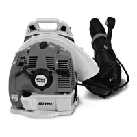
N Fit the spring (11) on the cam (10).
N Push cam (10) together with spring (3) onto setting
lever (1) as far as stop.
N Push setting lever (1) in direction of “0” and check that
the contact spring touches the yellow wire’s flag
terminal.
N Depress the lockout lever (8) and fit the throttle lever
(11) so that it engages the lockout lever (8).
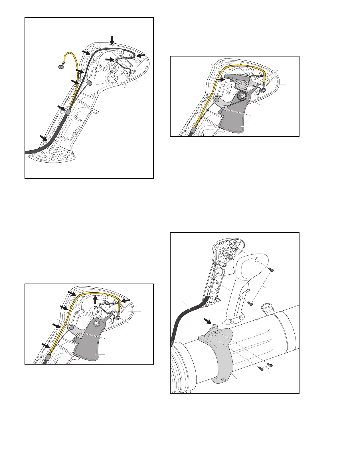
N Place handle molding (7) on handle molding (2).
N Insert and tighten down the screws (8a) firmly.
2
19
11
12
0000-GXX-6674-A0
9
10
11
20
12
21
2
0000-GXX-6676-A0
9
10
6
4
3
2
0000-GXX-6677-A0
2
7
18
12
8a
8b
0000-GXX-6678-A0

 Loading...