113MS 240, MS 260, MS 260 C
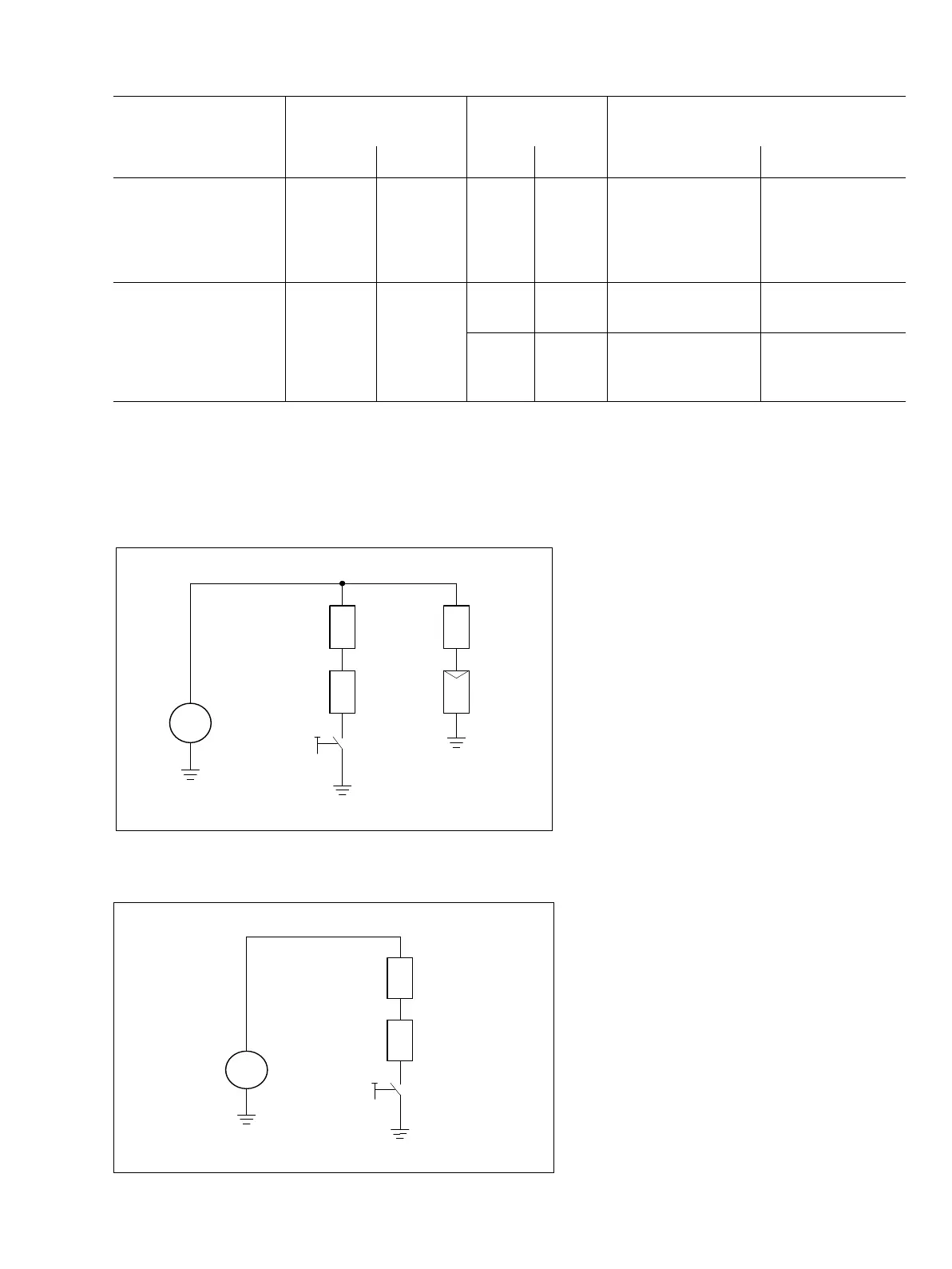
Circuit diagram
Carburetor and handle heating
system
Handle heating system
Component Ohmmeter connection
(use either test lead)
Resistance Ω If faulty
Lead 1 Lead 2 Spec. Actual Cause Remedy
Generator Connector
on
generator
wire
Ground 0.6 0.5 - 1 Generator OK
- Break in wire,
generator damaged
Install new
generator
0 Short circuit –
damaged insulation
Repair insulation
G Generator
1 Handlebar
2 Rear handle
3 Heater switch
4 Heating element (carburetor)
5 Thermostatic switch
219RA505 TG
G
1 4
5
2
3
G Generator
1 Handlebar
2 Rear handle
3 Heater switch
219RA615 TG
G
1
2
3

 Loading...