76 MS 240, MS 260, MS 260 C
12. Control Levers
12.1 Switch Shaft
The following positions can be
selected with the switch shaft:
– Position
0 = engine off
– ignition is switched off
– Position F = normal run position
– engine runs or may start in this
position
To move the switch shaft from F to
k or l depress the interlock lever
and throttle trigger at the same time.
– Position k = warm start
– warm engine is started in this
position
The switch shaft returns to the run
position when the throttle trigger is
operated.
– Position k = cold start
– cold engine is started in this
position
165RA281 TG
12.1.1 Removing and Installing
– Remove the air filter, b 14.1
– Remove the handle molding,
b 12.2
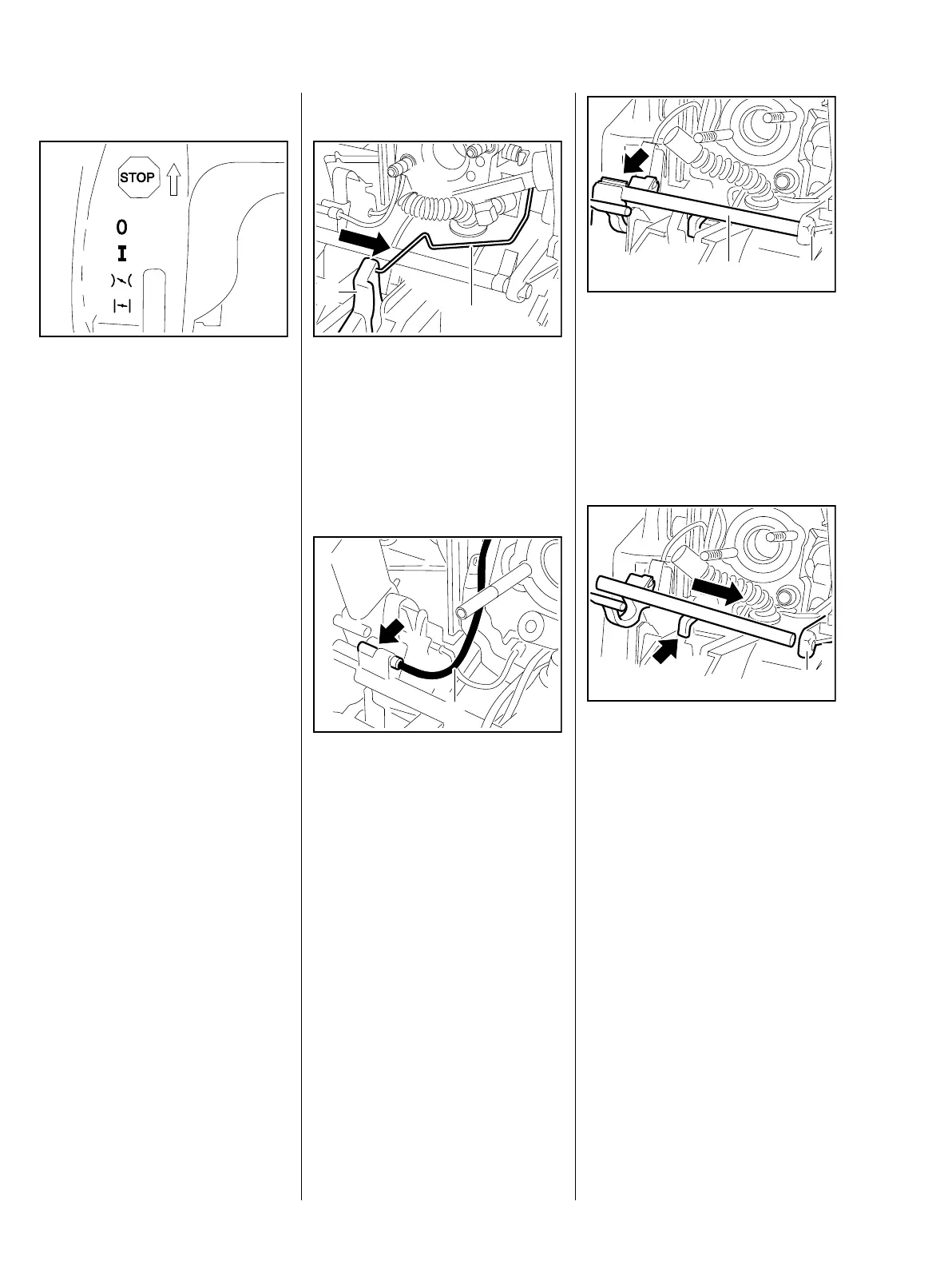
: Disconnect the throttle rod (1)
from the trigger (2).
: Pull terminal sleeve (arrow) of
short circuit wire (1) out of the
switch shaft.
165RA282 TG
1
2
165RA283 TG
1
: Pry the switch shaft (1) out of its
mount (arrow).
– Lift the switch shaft (1) a little and
pull it out of the mount (2).
– Check the switch shaft (1) and
replace if necessary
– Line up the switch shaft
– the arm (arrow) must point in
the direction of the throttle trigger.
: Push the switch shaft into the
mount (1).
165RA284 TG
1
2
165RA285 TG
1

 Loading...