91MS 240, MS 260, MS 260 C
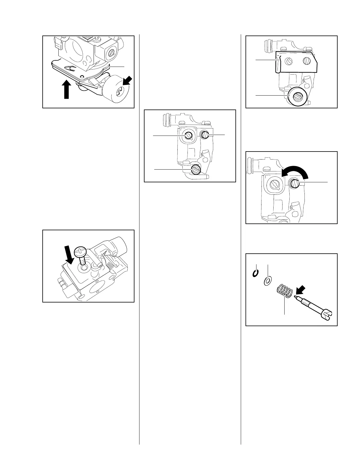
– Position the end cover (1) so that
the idle speed screw (arrow) is at
the same side as the adjusting
screws.
: Place the end cover (1) against
the carburetor body from below
so that the gasket and pump
diaphragm are still held in
position.
– Align the end cover (1) so that its
pegs engage the holes in the
carburetor body.
– Check that diaphragm and
gasket are properly seated.
: Insert screw and tighten it down
firmly.
– Reassemble all other parts in the
reverse sequence.
165RA362 TG
1
165RA363 TG
14.4.4 Choke Shaft / Choke
Shutter
The choke shutter is in the air filter –
see chapter on 'Air Filter' and
instruction manual.
14.4.5 Adjusting Screws
Grommets have been removed for
the sake of clarity.
There are three adjusting screws on
the carburetor:
H = high speed screw (1)
L = low speed screw (2)
LA = idle speed screw (3)
If the carburetor cannot be adjusted
properly, the problem may be the
adjusting screws.
The high speed screw H has a
limiter cap, which has to be
removed before the screw is
removed.
Always install a new limiter cap.
– Remove the carburetor, b 14.2
– See also carburetor
troubleshooting, b 4.6
165RA364 TG
1
2
3
: Pull off the grommets (1 and 2).
Low speed screw
: Take out the low speed screw (1).
– Inspect the sealing ring (1),
washer (2) and spring and
replace if necessary.
: Inspect the tip (arrow) for
damage or wear and replace the
screw (L) if necessary.
– Screw down the low speed screw
(L) as far as stop.
– Continue with high speed screw.
165RA365 TG
1
2
165RA366 TG
1
165RA367 TG
1 2
3