97MS 240, MS 260, MS 260 C
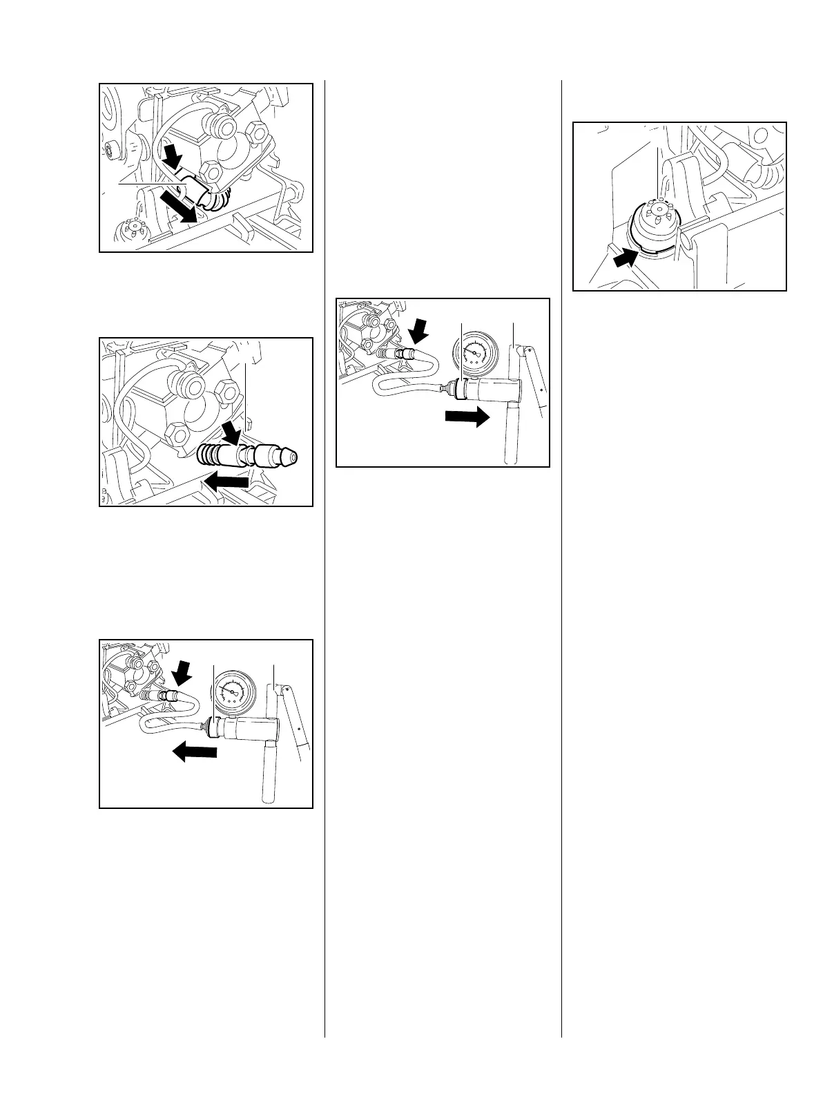
: Pull the fuel hose (1) off the stub
(arrow).
: Push the nipple (1)
0000 855 9200 into the fuel hose
(arrow).
Vacuum test
: Push the ring (1) to the left and
connect the pump (2)
0000 850 1300 to the nipple
(arrow) – subject the fuel tank to
a vacuum.
165RA390 TG
1
165RA391 TG
1
165RA392 TG
1
2
Equalization of pressure takes
place via the tank vent. There must
be no buildup of vacuum in the tank.
– Clean the area around the tank
vent.
– If necessary, install a new tank
vent or tank, b 14.7 or b 14.8.3
Pressure test
: Push the ring (1) to the right and
connect the pump (2)
0000 850 1300 to the nipple
(arrow)
– pressurize the fuel tank.
– Operate the pump (2) until the
pressure gauge indicates a
pressure of 0.5 bar. If this
pressure remains constant for at
least 20 seconds, the tank,
including the tank vent, is airtight.
If the pressure drops, the leak
must be located and the faulty
part replaced.
– Reassemble in the reverse
sequence.
165RA393 TG
1
2
14.7.2 Removing and Installing
– Remove the carburetor box
cover, b 9.2.1
: Pry out the tank vent (1) at the
recess (arrow).
Always install a new tank vent.
– Coat sealing ring of new tank
vent (1) with STIHL press fluid,
b 17
– Press the new tank vent (1) into
the bore as far as stop.
– Reassemble all other parts in the
reverse sequence.
165RA394 TG
1