77MS 240, MS 260, MS 260 C
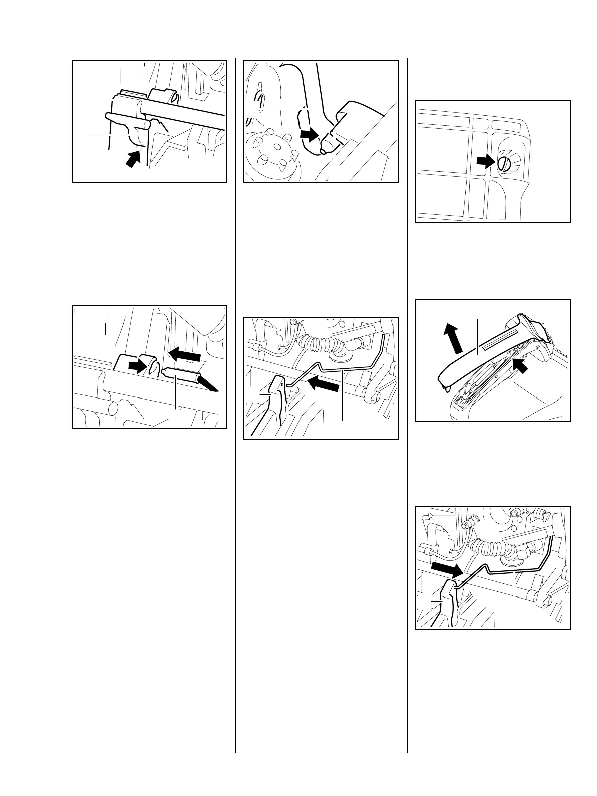
– Line up the switch shaft
– the lever (1) must locate in the
guide (arrow).
: Press the switch shaft into the
mount (2) until it snaps into
position.
: Push terminal sleeve (1) of short
circuit wire into the bore (arrow)
as far as stop.
165RA286 TG
1
2
165RA287 TG
1
– The contact spring (1) must butt
against the switch shaft's (2)
guide.
: Move switch shaft to "
0" –
contact between the short circuit
wire and contact spring (arrow)
must be made.
: Attach the throttle rod (1) to the
trigger (2).
– Fit the handle molding, b 12.2
– Check correct position of short
circuit wire,
b 9.6.2
– Check operation.
– Reassemble all other parts in the
reverse sequence.
– Tightening torques, b 3.5
165RA288 TG
1
2
165RA335 TG
1
2
12.2 Throttle Trigger/Interlock
Lever
– Remove the air filter, b 14.1
: Take out the screw (arrow).
: Remove the handle molding (1).
The interlock lever (arrow) may pop
out.
: Disconnect the throttle rod (1)
from the trigger (2).
165RA289 TG
165RA290 TG
1
165RA282 TG
1
2

 Loading...