73MS 240, MS 260, MS 260 C
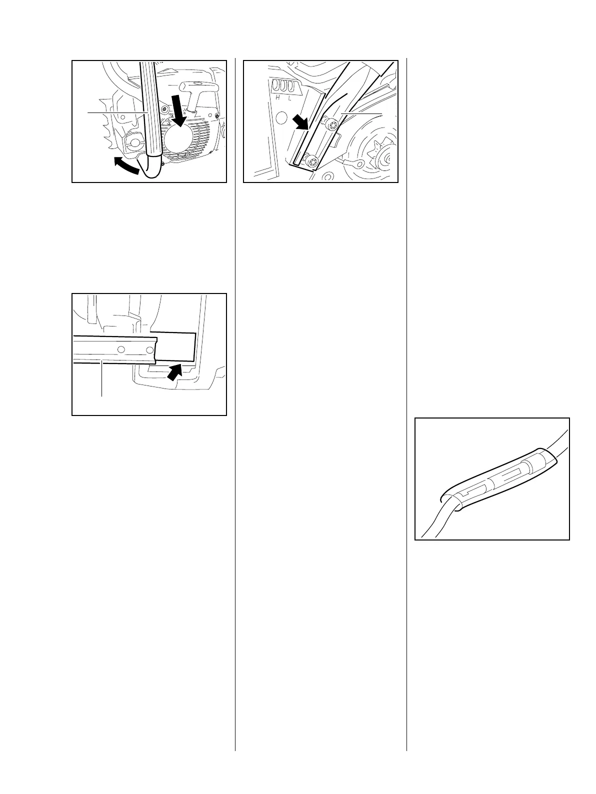
: Push the handlebar (1) out of its
seat on the underside of the
machine.
– Remove the handlebar (1), check
it and replace if necessary.
: Position the handlebar (1) in its
seat (arrow) and insert the
screws.
165RA264 TG
1
165RA487 TG
1
: Position the handlebar (1) in its
seat on the side of the machine
(arrow) and insert the screws.
– Check that the handlebar is
properly seated and then tighten
down all four screws firmly.
– Reassemble all other parts in the
reverse sequence.
– Tightening torques, b 3.5
11.6 Handlebar with Handle
Heating
The handlebar in these versions is
equipped with a heating system –
the electrical wires have to be
disconnected.
– Troubleshooting, b 15.3.1
Apart from the electrical
connections, the removing and
installing procedures are the same
as for the handlebar without
heating, b 11.5.
– Remove the carburetor, b 14.2
165RA266 TG
1
– Take out the annular buffer/tank
housing mounting screws.
Annular buffer at ignition side,
b 11.3.
Annular buffer at clutch side,
b 11.2
– Remove the interlock lever,
b 12.2
– Remove the switch shaft,
b 12.1.1
– Push the manifold out of the tank
housing, b 14.6.1
– Pull off the impulse hose,
b 14.6.2
– Remove the heater switch,
b 15.4
– Remove the ground wire from the
housing cover, b 15.4.1
– Lower the tank housing for easier
access.
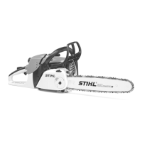
During all the following procedures:
: To reduce the risk of a short
circuit, make sure the insulating
tubes completely cover the
connections.
165RA267 TG