26 MS 240, MS 260, MS 260 C
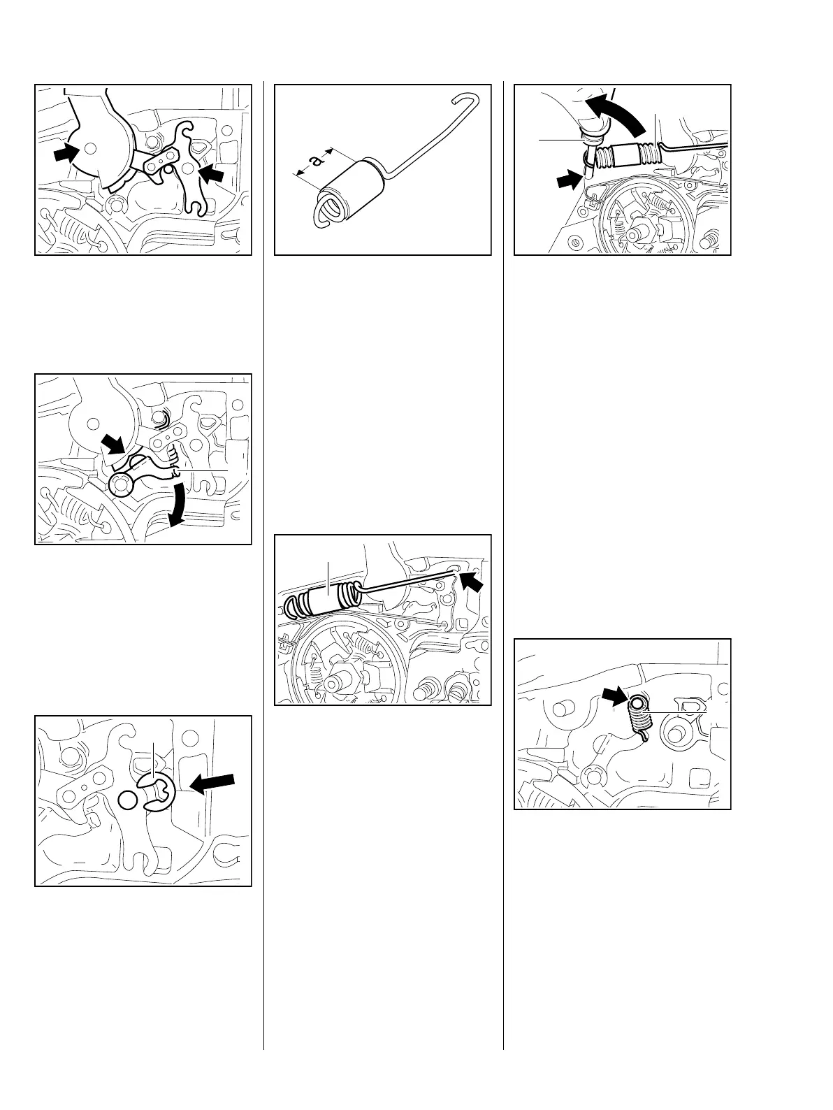
: Lift the bearing boss of the hand
guard and the brake lever a little
and position them over the pivot
pins (arrows).
: Turn the cam lever (1) to one side
until the cam of the hand guard
(arrow) slips passed it.
– Push the hand guard bearing
boss and the brake lever on to
the pivot pins.
: Fit the E-clip (1).
165RA054 TG165RA055 TG
1
165RA056 TG
1
: The turns of brake spring must be
tightly against one another in the
relaxed condition. If this is not the
case, replace the brake spring.
Check the correct position of the
protective hose – it must be
centered in the spring.
a = 20 mm
If the groove in the brake spring
anchor pin is worn, install a new pin,
b 7.5
: Attach the brake spring (1) to the
brake lever (arrow).
165RA057 TG
165RA058 TG
1
: Use the assembly tool (2)
1117 890 0900 to attach the
brake spring (1) to the anchor pin
(arrow).
– Reassemble all other parts in the
reverse sequence.
– Tightening torques, b 3.5
– Lubricate the brake lever, b 17
7.4 Cam Lever
The cam lever defines the locked
position of the hand guard.
– Remove the brake lever, b 7.3
: Disconnect the spring (1) from
the anchor pin (arrow).
165RA059 TG
2
1
1
165RA060 TG

 Loading...