75MS 240, MS 260, MS 260 C
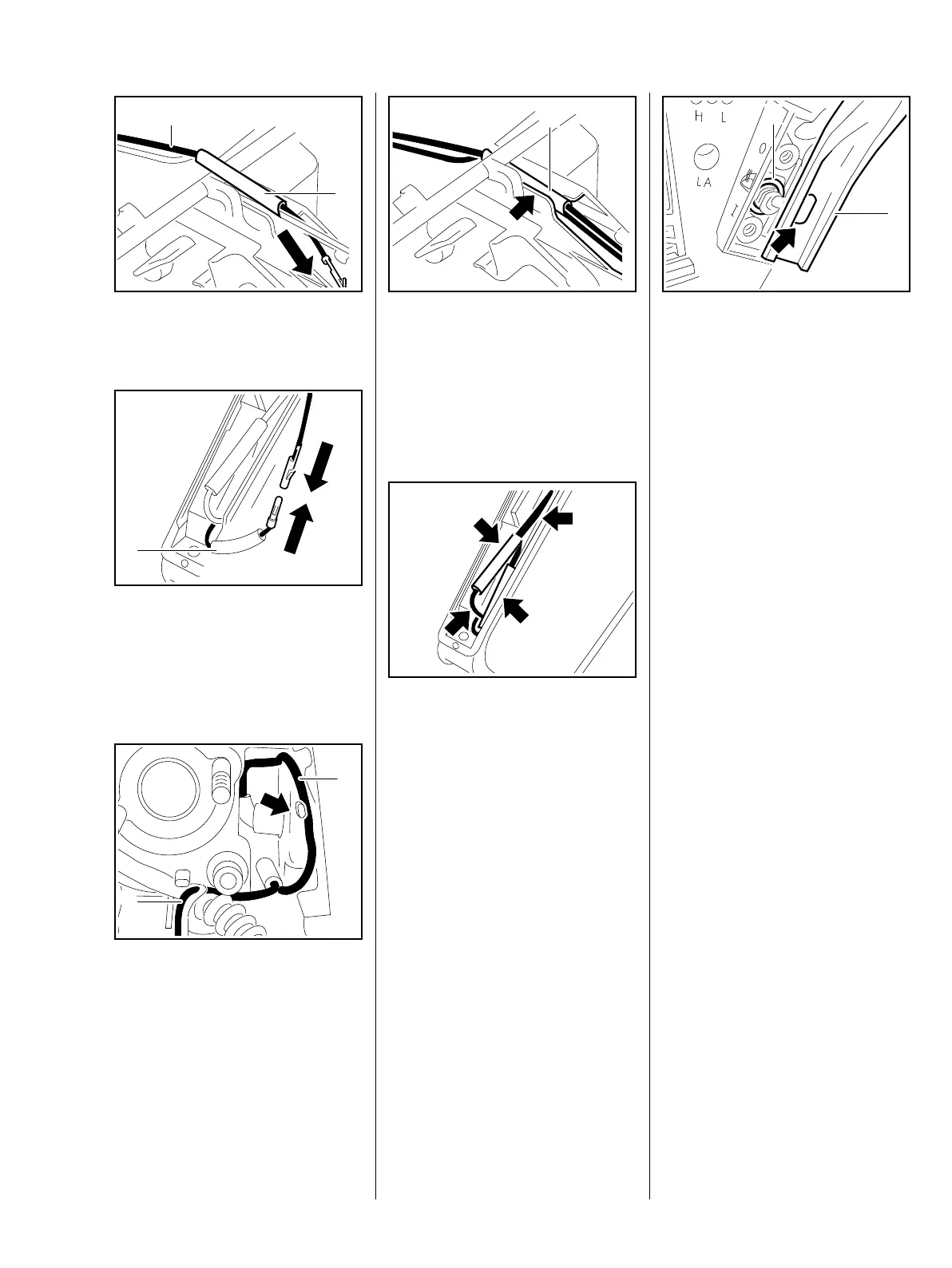
: Push the wire (1) through the
insulating tube (2).
: Push the pin and socket together
until they lock.
– Push the insulating tube (1) over
the connectors.
: Push the wire (1) into the guide
(arrow) – position the wire snugly
against the housing.
: Position the wire (2) behind the
fuel hose.
165RA276 TG
1
2
165RA277 TG
1
165RA330 TG
1
2
: Push the wires with the insulating
tube (1) into the guide.
The wires and insulating tube (1)
must not project
– risk of chafing on switch shaft or
throttle rod.
– Position the wires without loops.
: Arrange the connectors and
wires (arrows) on the heating
element so that they are not
pinched.
165RA278 TG
1
165RA279 TG
– The ground wire ring terminal (2)
must be in position on the heater
switch.
: Position the handlebar (1) so that
the heater switch engages the
opening (arrow).
– Secure the handlebar, b 11.5
– Reassemble all other parts in the
reverse sequence.
– Tightening torques, b 3.5
165RA280 TG
1
2