115MS 240, MS 260, MS 260 C
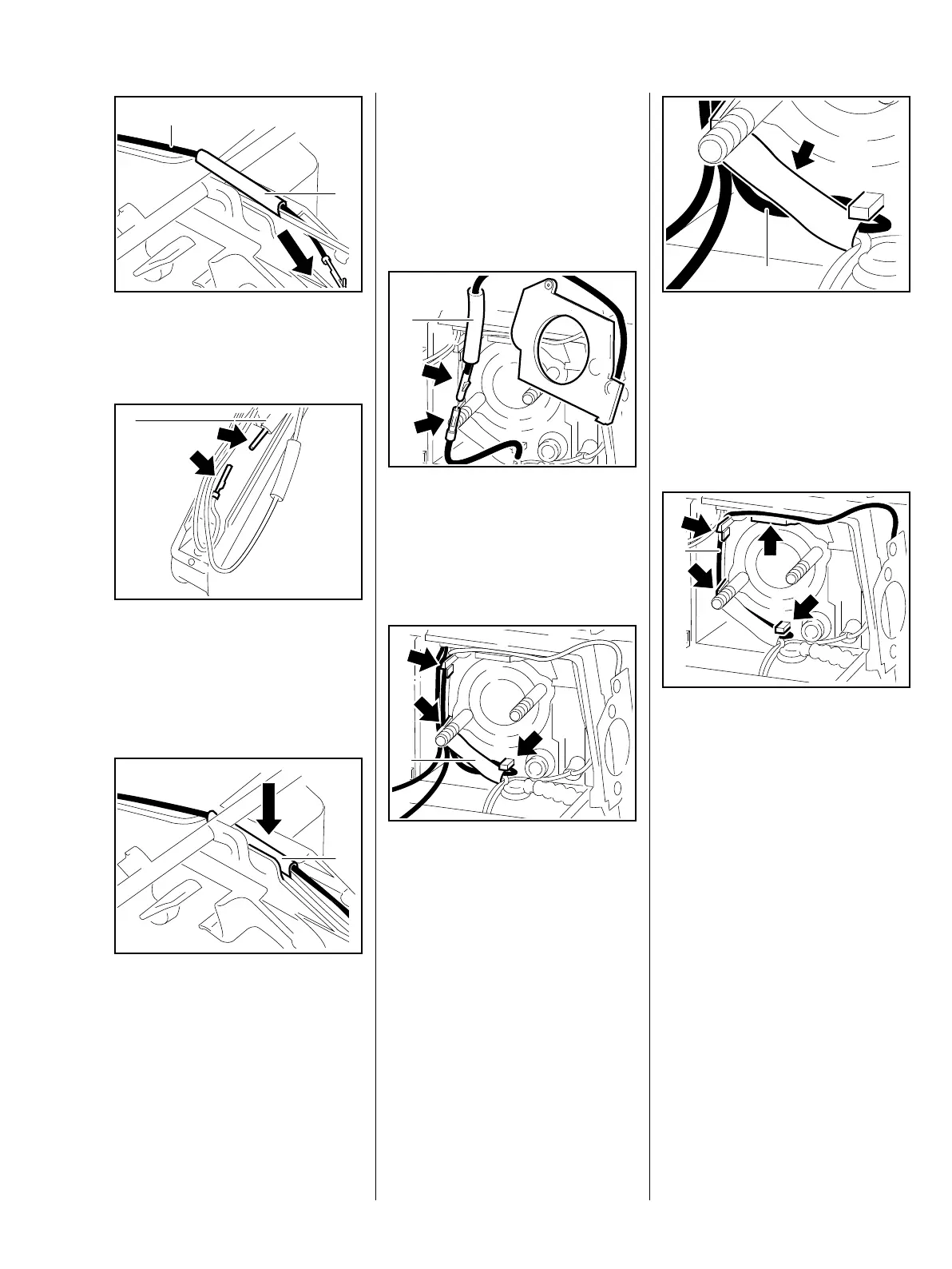
: Push the heating element/wiring
harness wire (1) through the
insulating tube (2).
: Push the pin and socket (arrow)
together until they lock.
– Push the insulating tube (1) over
the connector.
: Push the wires with the insulating
tube (1) into the guide.
165RA276 TG
1
2
165RA435 TG
1
165RA454 TG
1
The wires and insulating tube (1)
must not project – risk of chafing on
switch shaft or throttle rod.
– Install the switch shaft, b 12.1.1
– Install the interlock lever, b 12.2
: Push the pin and socket (arrow)
together until they lock.
– Push the insulating tube (1) over
the connector.
– Push the wire (1) and connector
(1) into the guides (arrows).
165RA407 TG
1
165RA089 TG
1
: Position the wire (1) behind the
pin and socket connector (arrow).
– Install the short circuit wire,
b 9.6.2
– Install the carburetor, b 14.2
: Push wire (1) of the carburetor
heating element into the guide
(arrow).
The wire must not touch the lever on
the throttle shaft.
– Reassemble all other parts in the
reverse sequence.
– Tightening torques, b 3.5
165RA452 TG
1
165RA491 TG
1

 Loading...