39MS 240, MS 260, MS 260 C
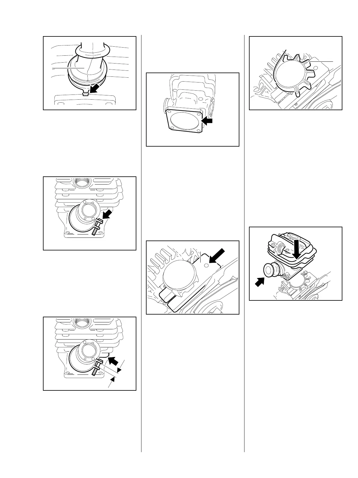
– Push the manifold (1) on to the
intake stub.
: Line up the manifold (1)
– the tab must be pisitioned as
shown in the illustration (arrow).
– Position the hose clamp so that
the screw head (arrow) points
toward the clutch side.
: Push the hose clamp on to the
manifold.
– Turn the hose clamp until the
screw head is below the lower
cylinder fin (arrow).
165RA034 TG
1
165RA071 TG165RA035 TG
a
: Tighten the screw until the gap
"a" between the two ends of the
hose clamp is about 5 to 6 mm.
: Inspect and clean the sealing
face (arrow) and remove any
gasket residue.
– Check the sealing faces on the
cylinder intake and exhaust ports.
The sealing faces must be in perfect
condition. If the sealing faces are
damaged, install a new cylinder.
: Slide the wooden assembly block
(1) 1108 893 4800 between the
piston and crankcase.
165RA072 TG165RA073 TG
1
– Lubricate the piston, piston rings
and cylinder wall with oil, b 17
: Use the clamping strap (1)
0000 893 2600 to compress the
rings around the piston.
– Check correct installed position
of rings, b 8.8
Apply the clamping strap (1) so that
the piston rings do not project
beyond the cylinder wall.
: Align the cylinder so that the
intake port (arrow) points toward
the rear handle.
While sliding the cylinder over the
piston, hold the clamping strap
tightly around the piston so that the
rings do not project – they might
otherwise break.
: Slide the cylinder over the piston,
the clamping strap moves
downwards at the same time.
165RA074 TG
1
165RA079 TG
 Loading...