The rack or cabinet should be properly secured to prevent tipping. Equipment that is
installed in a rack or cabinet should be mounted as low as possible, with the heaviest units
lower down, and lighter units toward the top.
Precautions:
Ensure that the power circuits are properly grounded and use the power cord supplied with the
SatLink VSAT IDU to connect it to the power outlet.
If your installation requires a different power cord than the one supplied, ensure that the cord used is
certified as indicated by the stamped or embossed logo of the electrical safety authority in your
country.
If the on/off switch on the back panel is difficult to reach when the unit is fitted in the rack, ensure
that the power outlet into which it is plugged can be reached so it may be unplugged if necessary.
Ensure that the unit does not overload the power circuit, wiring, or over-current protection. To
determine the possibility of overloading the supply circuits, add together the amperage ratings of all
devices installed on the same circuit as the VSAT IDU and compare the total with the rating limit for
the circuit. The maximum amperage ratings are usually printed on units near their power connectors.
Do not install the VSAT IDU in a location where the operating ambient temperature may exceed
45°C.
Ensure that the airflow around the sides and back of the SatLink VSAT IDU is not restricted.
The SatLink 1900/1901/1910/2900 can be mounted in any EIA-standard 19-inch telecommunications
rack or cabinet. The STM SatLink 1000 and 2000 need to be placed on a shelf if either is to be placed in a
rack.
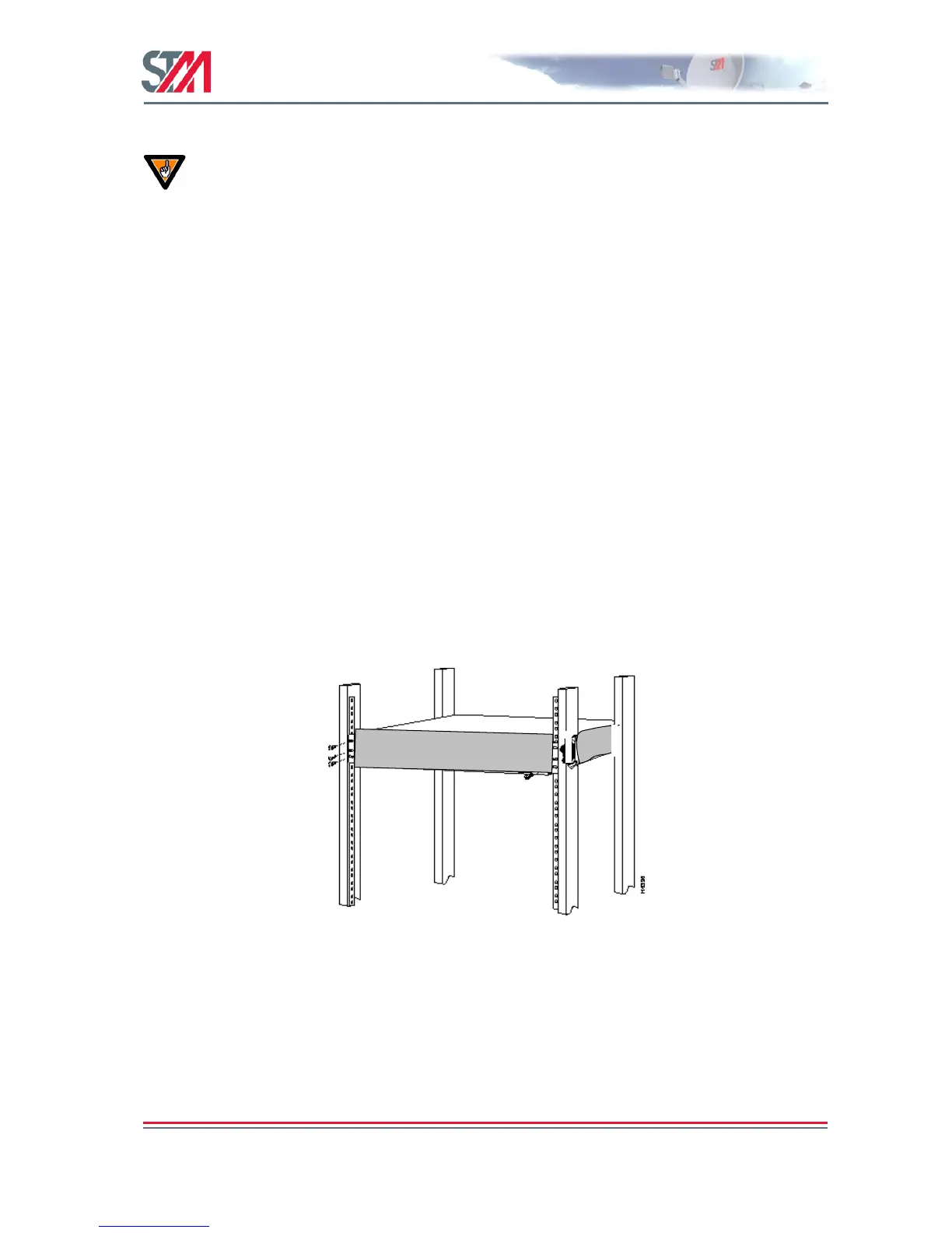
Use a Torx screwdriver and attach the mounting brackets to the router with the screws supplied. Hold the
unit securely, brackets attached, and move it vertically until the rack holes line up with the bracket
notches, then insert and tighten the four screws holding the brackets to the rack.
Figure 11: Rack Mounting
3.4 ODU Installation
Install the ODU as described in Appendix F, reference [1] and the antenna installation manual. When
installing the SatLink 403x transceiver, please check Table 22 in Appendix G to determine whether an
adapter is required to interface the antenna feed horn.