Publication no. 101557
Rev 14.1.1-2
Copyright 2006-2012 – STM Group, Inc.
White: lights steadily when power switch is on and unit is powered. Flashes when
loading software.
Red: lights steadily when an error event occurs and during reboot.
White: flashes when the receiver is searching for the carrier.
Lights steadily when receiver is on and functioning properly.
Flashes when IP packets are received from the Satellite Interface (the Hub).
White: flashes rapidly when a continuous wave (CW) is transmitted.
Lights steadily when the VSAT is logged on to the DVB-RCS Hub.
Flashes when IP packets are transmitted to the Satellite Interface (the Hub).
White: lights steadily when Ethernet connectivity is OK.
Flashes slowly when Ethernet packets are transferred via the Ethernet interface.
Table 7: SatLink 2900 Front Panel LEDs
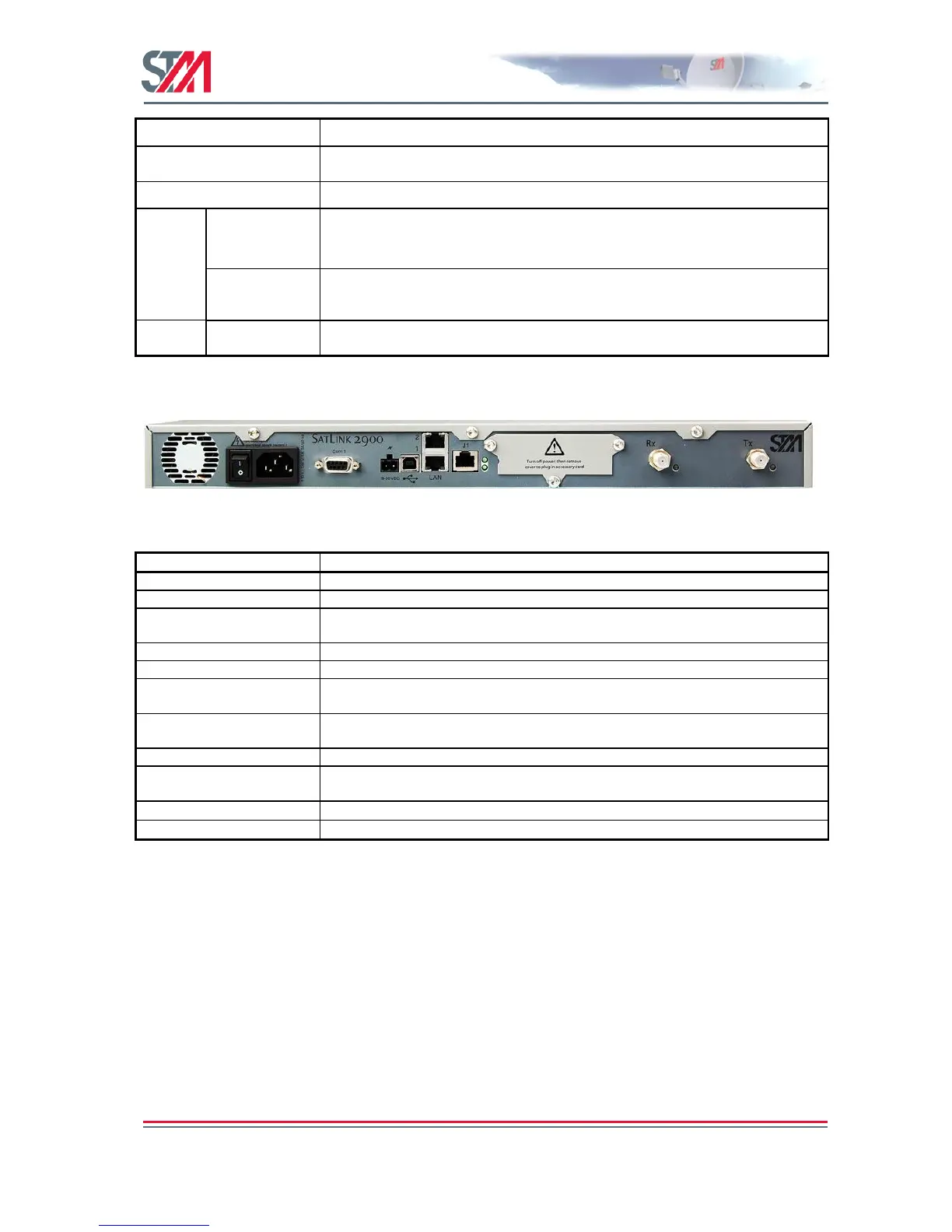
Figure 10: SatLink 2900 Rear Panel
Standard recessed plug for 110-240VAC power cord.
RJ45 connector for IP traffic to connect to a PC, Ethernet switch, IP router etc.
10BASE-T, 100BASE-T or 1000BASE-T mode is detected automatically.
Connector for alternative 24VDC (19-36VDC) power supply. Typically used when
powered from solar panels.
Nine pin connector for connecting CLI interface to a computer‘s DB-9 serial
interface.
Digital I/O used for Mobile applications Please refer to section 19.1.2 for more
information.
Coaxial 75 F-type jack for the cable to the LNB.
Coaxial 75 F-type jack for the cable to the BUC.
Table 8: SatLink 2900 Rear Panel
3.3 IDU Installation
3.3.1 On Desktop or Shelf
Place the VSAT IDU on a flat, stable surface, such as a desktop or shelf, close to the PC or network
device to which it will be connected. Keep its top, bottom, and all sides unobstructed to ensure free
airflow. Rubber feet on the bottom provide adequate clearance. Ensure that there is at least 10 cm
clearance at the back to allow room for cable connections.