Publication no. 101557
Rev 14.1.1-2
Copyright 2006-2012 – STM Group, Inc.
G.1 Mounting the Feed Horn Interface Adapter on the SatLink 403x
Antenna feeds with option B hole patterns will require use of the SatLink 4901 adapter kit (STM P/N
107268) for interfacing the SatLink 403x. Use the following procedure:
1. Insert the rubber gaskets supplied with the adapter on both sides of the adapter.
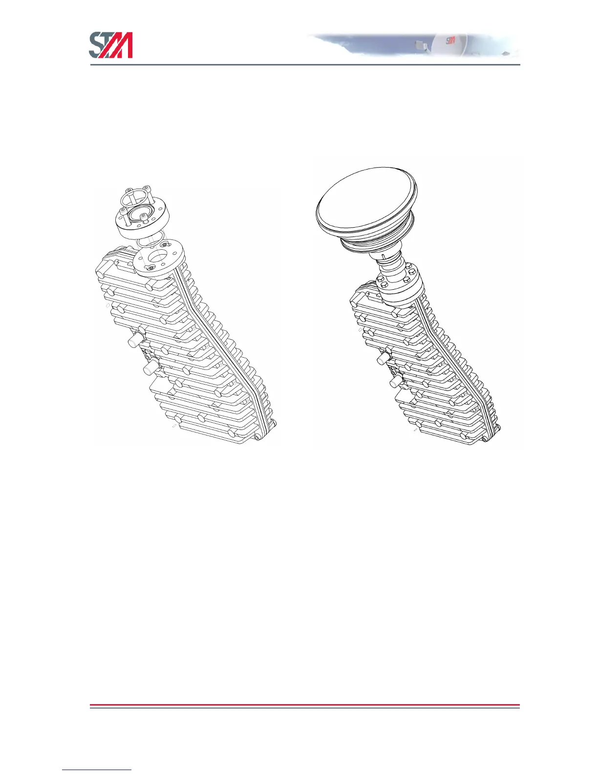
2. Use the 4 UNC screws to fasten the adapter to the SatLink 403x flange as shown in Figure 63.
3. Fasten the SatLink 403x to the antenna feed horn as shown in Figure 64.
Figure 63: Mounting of SatLink 4901 (STM
P/N 107268) on SatLink 403x. Remember to fit
rubber gasket on both sides of the adapter to
prevent moisture intrusion. Fasten the adapter
using 4 UNC screws supplied with the SatLink
403x. Hand tighten with Allen key.
Figure 64: Mount the antenna feed to the
adapter and fasten using M4 screws.
G.2 Upgrading Existing VSAT Installations
When upgrading an existing VSAT site from a configuration with an antenna listed in Table 22 to a DVB-
RCS site configured with the SatLink 403x transceiver, the antenna will normally be configured with a
feed horn with the option B hole pattern (Figure 62) and an OMT. In order to fit the SatLink 403x to the
antenna from the VSAT installation, do the following:
1. Remove the OMT. This part is not used when installing the SatLink 403x transceiver.
2. Use the adaptor SatLink 4901 (STM P/N 107268) to interface the SatLink 403x to a feed horn with
interface C120 / 4 screws as shown in Figure 63 and Figure 64.
Alternatively, feed horns (Andrew P/N 61-00233-01) with interface option A for Andrew 96 cm and
1.2 m antennas can be ordered separately.