928 Mixing Console
Jumpers E 3/3
Edition:
07.02.01
APPLIES TO VERSION 2: Each input unit is equipped with two remote control relays. The nor-
mally-open contacts of these relays are terminated on the 9-pin D-type
connector of the rear panel.
The relay contacts can be used for remote control or signalization. The
function and the behavior of the remote control can be varied with jump-
ers J3, J4, J5, and J11.
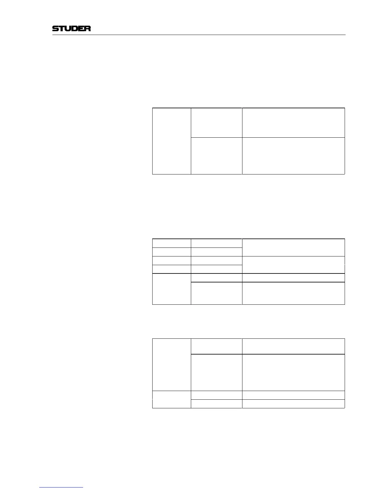
Remote control output
J3
1-2 Start pulse on the REM output of the remote
control.
Stop pulse on the STOP output of the remote
control.
2-3 (default) Latching contact on the REM output of the remote
control for as long as the fader is open and the
ON key is active.
Stop pulse on the STOP output of the remote
control.
Remote control key With the START key the fader start can be prepared or initiated. If the
key is pressed when the fader is closed (dim backlight of the key) the
fader start command is executed as soon as the fader is opened and the
ON key is activated.
If the START key is pressed when the fader is already open and the ON
key is active, it immediately executes the fader start command.
J4
1-2 (default)
START key is active
J11
closed
J4
2-3
START key is disabled, fader start depends only
on the fader and the ON key
J11
open
J5
1-2 START key generates start pulses
2-3 (default) START key functions as a latching start/stop key
and enables or disables fader start activation with
the fader control
Signalization The 928 mixing console features two signaling buses that are used for
on-air signaling and deactivation of the studio speakers.
J12
1-2
When the microphone channel is opened, the
CR monitor is dimmed (DJ mode)
2-3 (default)
When the microphone channel is opened, the
studio speaker is switched off, and the studio
on-air lamp is activated if the ON AIR signal is
available or the STUDIO ON key in the signaling
unit is pressed.
J13
1-2 (default)
Microphone input acts on the signaling buses.
2-3 LINE input acts on the signaling buses