© 2022 STYPE; ALL RIGHTS RESERVED.
22
09 FOLLOWER NETWORK
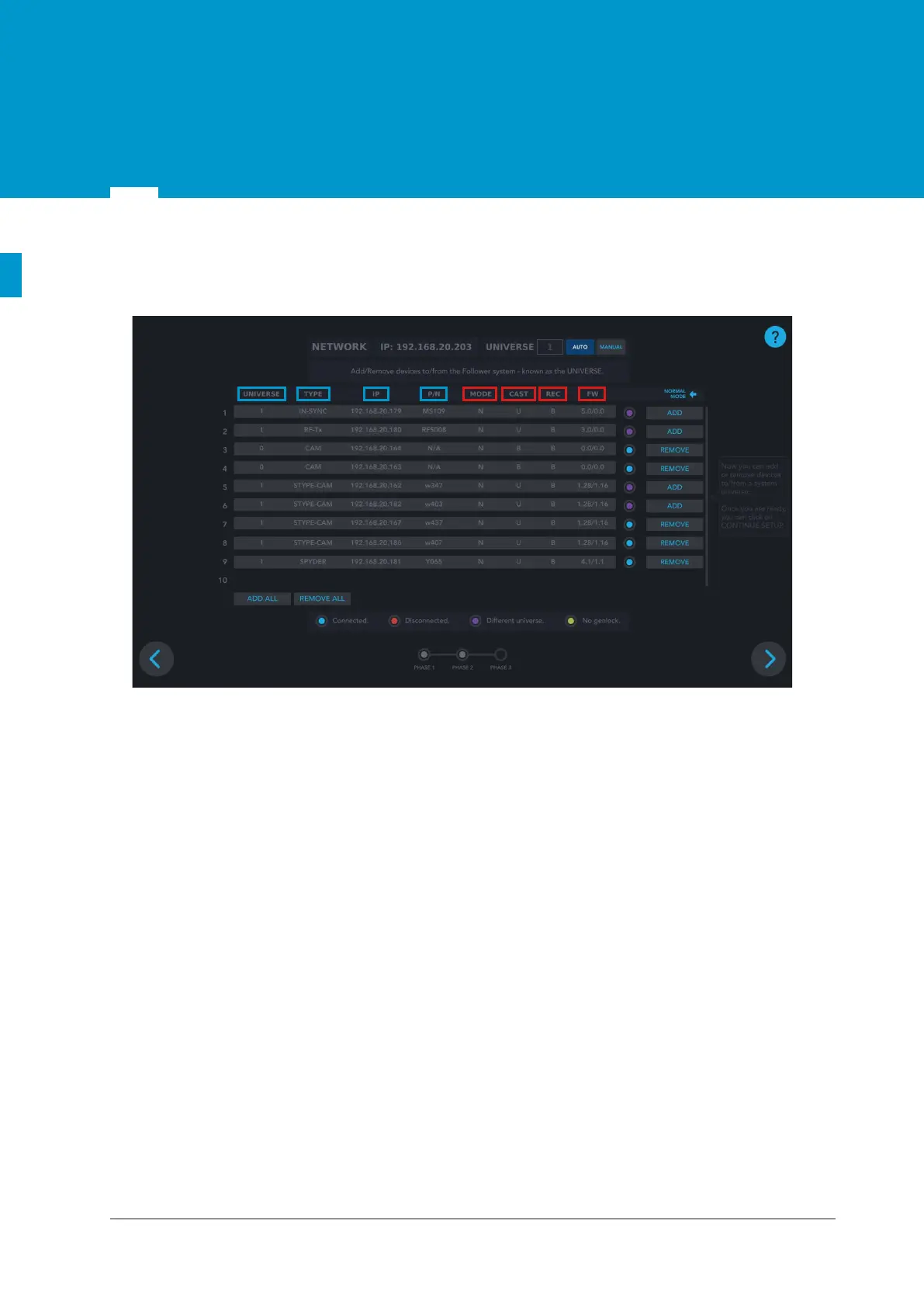
9.1 Network setup screen overview
Data visible in NORMAL MODE:
• UNIVERSE - the number by which the specific Follower system is defined and it enables differentiating
between multiple different Follower systems connected to the same POE switch. Numbers from 1 to
255 define the universe, while 0 presents an undefined universe. In chapter 9.2.2 will be explained how
to assign a universe number to the part.
• TYPE -the type of the connected part: - IN-SYNC (MainSyncUnit)
- RF-Tx (Radio)
- STYPE-CAM
- SPYDER.
• IP - IP address of the specific part assigned by the DHCP server.
• P/N - part number of the connected part.
Data visible when DEBUG MODE is expanded:
• MODE - Normal (N) or Bootloader (B). Normal is the operational mode, while Bootloader is the mode
for firmware upgrade of SyncBox and Spyder module.
• CAST -
the way the specific part is sending the data in the network. It can be broadcast (B) or unicast (U).
• REC
- the way the specific part is receiving the data in the network. It can be broadcast (B) or unicast (U).
• FW - firmware version of the part.
Figure 9.1 Network setup screen