SS100 Build Manual (Export Edition) Rev 10 November 2013
5.4.1 Front end wiring loom
Start by identifying the front end of the loom for the headlamps and engine and pass this through the servo
plate, to locate loom in correct position take the headlamp/horn connections (one or two white plugs for each
side) and place them behind and on each side of the chassis cross member that runs below the radiator. “P”
clip the front loom under the cross member in this position working back towards the servo plate pulling any
slack back through the servo plate.
5.4.2 Rear and gearbox loom
The wires for the rear electrical items and gearbox exit the main loom just above the relays, these need to
tied to the main loom down to the servo plate where the rear loom can head backwards through the chassis
openings and the gearbox loom can be attached to the angle chassis box section towards the gearbox.
Other cables in this area are White/Purple which goes to the fuel pump and Green with Green/Purple which
has to be taken forward through the servo plate for the brake lamp switch. Some of the same fixing points as
those used to secure the brake lines can be used by mounting 2 “P” clips back to back. Make sure that the
various connections are in the correct positions.
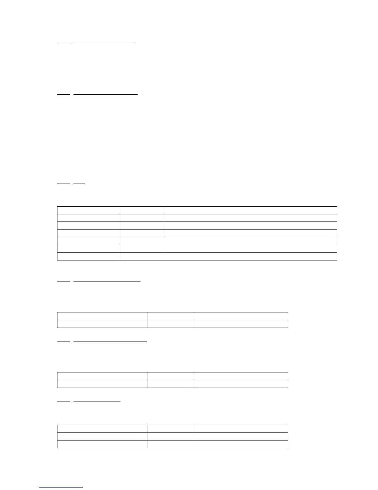
At this stage the following parts can be fitted if not already and connections made to them (use crimp or
solder connectors where required):
5.4.3 Coil
The coil should be bolted in an upright position near to the distributor, there are spare threaded holes in the
engine block, which can be used to mount a plate for the coil to be mounted on.
+12v feed to electronic ignition distributor (optional)
Feed to mechanical distributor (not used on electronic ignition)
The other end of above wire needs to be connected to the distributor/points
-12v feed to electronic ignition distributor (optional)
5.4.4 Electric oil gauge sender
If using electrical gauges the oil pressure sensor should be fitted into one of the six blanks in the oil ways in
the right side of the engine block, these run from front to back just above the join between sump and engine
block.
Oil pressure sender connection
-12v Feed to oil pressure gauge
5.4.5 Electric water temp sender
If using electrical gauges the water temperature sensor needs to be fitted in the inlet manifold, there is a
position for this on the underside at the front of the manifold, fit this using PTFE tape or similar to save
small leaks from the thread of the switch.
Water temp sender connections
-12v Feed to water temp gauge
5.4.6 Stop lamp switch
The stop lamp switch is fitted into a four way brake union in the feed to the front brake pipes, this has two
terminals which can be connected either way around.
Stop lamp switch connections
+12v Ignition switched feed
+12v Switched output to lamps