SS100 Build Manual (Export Edition) Rev 10 November 2013
5.4.7 Cooling fan and switch
Install the cooling fan switch into the top of the radiator using a copper or aluminum washer to seal. If not
already fitted, install cooling fan to front of radiator. Insert supplied rubber bushes between fan and radiator
before pushing the special zip ties through the radiator core, fit four more rubber bushes between radiator
core and zip tie catch plate. Pull zip tie plates tight and cut excess tie off, make sure ends are not left sharp.
The cooling fan and switch can now be connected.
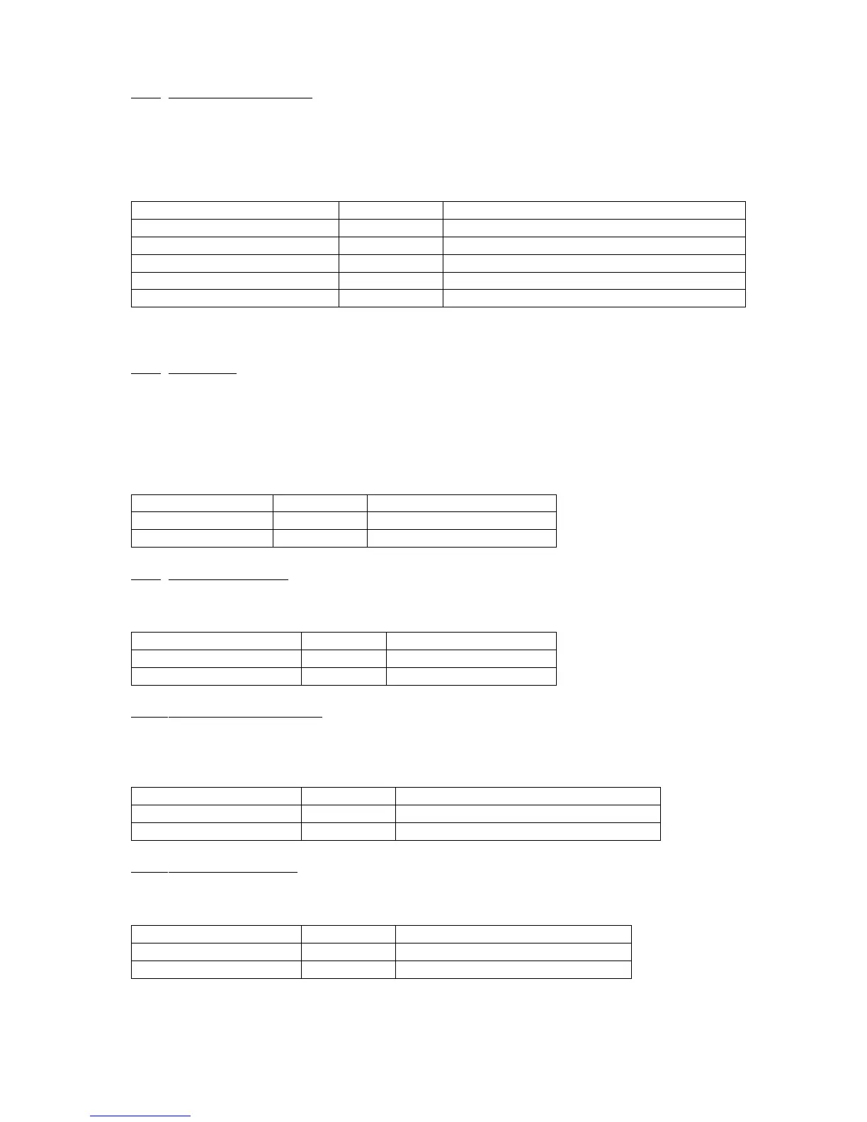
Cooling fan switch connections
-12v trigger to cooling fan relay
-12v fly lead, connect eyelet end to chassis earth
Note, please check fan pushes air through radiator, and if fan rotates the wrong way please reverse blue and
black wires.
5.4.8 Fuel pump
The Fuel pump needs to be mounted using the two rubber mounts supplied to avoid excess vibrations, it is
mounted inside the main chassis near the clutch master cylinder. When wiring the fuel pump remember to
run an earth lead from the pump body to the chassis. It will not run otherwise as the rubber mounts insulate
it. An earth wire with two eyelets is supplied with the pump for doing this, make sure the metal is clean on
the chassis where you fit the earth wire as it will not work through the powder coat, protect this area with
grease after fitting earth wire.
5.4.9 Overdrive solenoid
On the compact four gearbox with overdrive, the overdrive solenoid is fitted on the left side of the gearbox
and is a cylindrical solenoid with one cable exiting from its rubber boot.
5.4.10 Overdrive inhibit switch
On the compact four gearbox with overdrive, the overdrive inhibit switch is fitted in the top of the gearbox, it
is the front of two switches and has two terminals which can be connected either way around. Its job is to
allow the overdrive to operate only when in forth gear.
+12v Inhibit switch control to dash switch
5.4.11 Reverse lamp switch
On the compact four gearbox the reverse lamp switch is the rear most switch in the top of the gearbox, it has
two terminals, which can be connected either way around.
+12v Switched feed to reverse lamp