Appendix 1.1 Fuses and relays.
Fus
es
Bulkhead mounted fuse box, this could be mounted either way up.
Right hand front and rear side lamps and dashboard illumination (22).
Left hand front and rear side lamps (23).
Rear fog lamp (34).
Headlamp dip beam (25).
Headlamp main beam (45).
Live feed for hazard lamps, Horn, main beam flash (39).
Ignition feed 1 (30).
Ignition feed 2 (31).
The ignition feed fuses can vary between the two fuses the typical layout is:
Ignition fuse 1 (30) Ignition feed 2 (31).
Low charge warning lamp. Heater fan.
Tachometer. Relay feeds for cooling fan and fuel pump.
Wiper motor. Indicators.
Overdrive switch feed.
Electric gauge feeds.
Low brake fluid/handbrake warning
Brake lamps.
Reverse lamp.
Line fuses.
There are two or three line fuses,
Main power fuse on bulkhead.
Spot lamp fuse mounted to relay pack.
Optional, behind dash for Auxiliary socket. Typical four pin relay.
Rel
ay fuses.
Three of the relays also have fuses these are;
Overdrive relay.
Fuel pump relay.
Cooling fan relay.
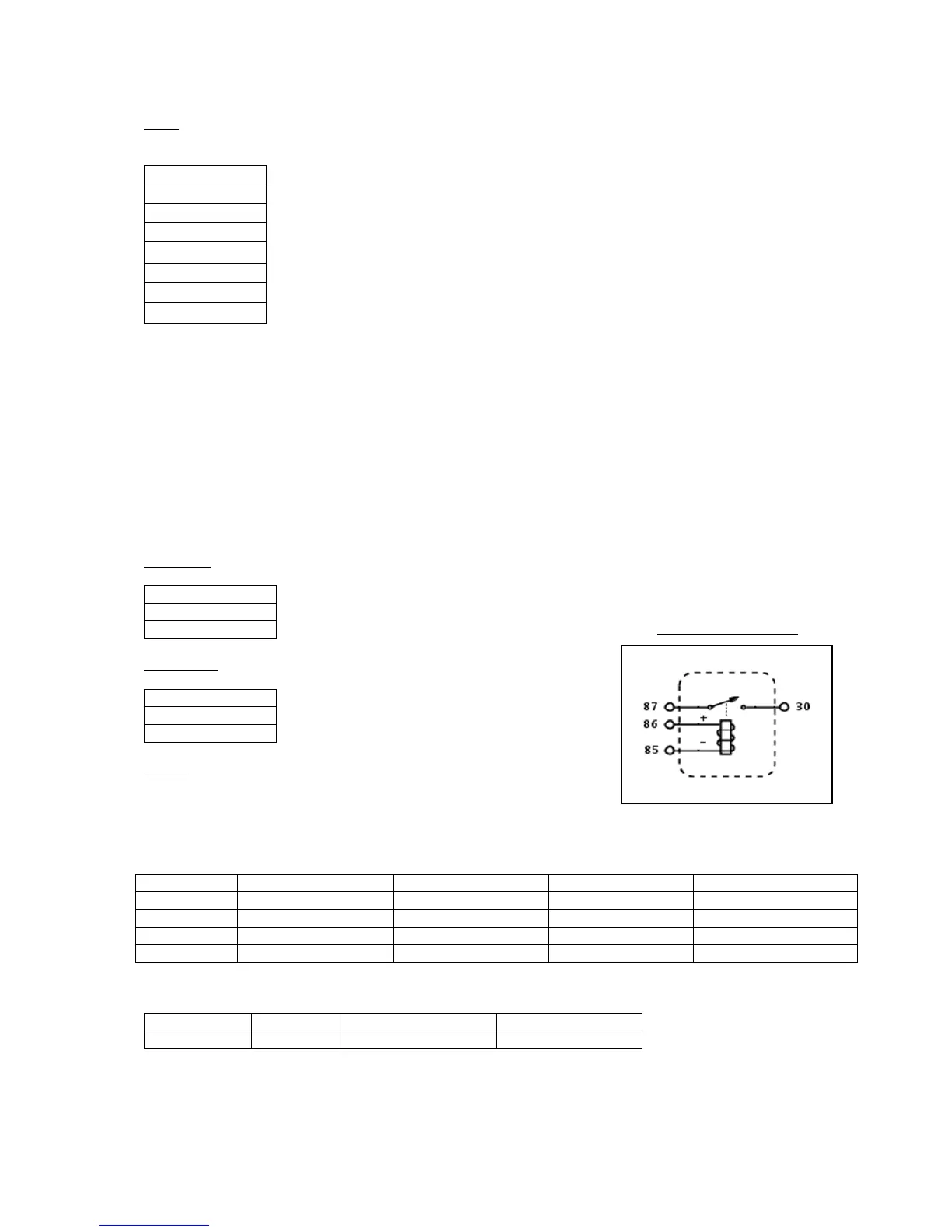
Relays.
Above left is a typical four-pin relay, this works like an electric switch.
Connecting pin 85 to +12v and pin 86 to -12v operates the coil and
connects pin 87 to pin 30. Pins 85 and 86 and pins 30 and 87 can be connected either way around in a standard
four-pin
There is also a three pin flasher relay this connected as follows: