SUNFAR C300 59
C300 series of non-sensor current vector-control inverter manual
have not stop, will start up directly according to detect result.
Start frequency :It is fit for system, which is big inertia, heavy load and high start
torque.
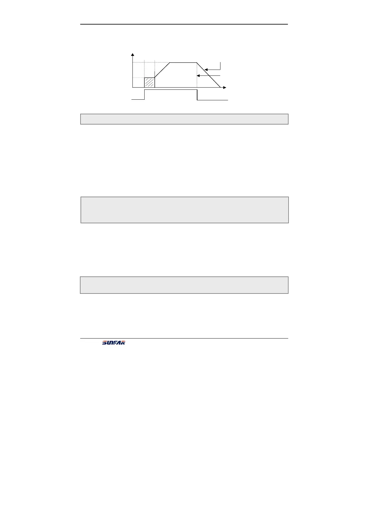
0: Decelerate mode
Inverter will gradually decrease output freq. to 0 according to Dec time when
stopping.
1: Uncontrolled stop
Inverter will output zero freq. and lock output signal when stop, so motor will stop
uncontrolled.
If user needs restart motor before motor stop completely, function of detection
speed and restart must be valid when inverter stops uncontrolled.
Start mode and stop mode is shown as fig6-16.
It is used for setting DC braking parameters when stopping, shown as fig6-7.
When output freq. is lower than setting freq. of Parameter F4.4, inverter will lock
output and start DC braking function after waiting setting time of parameter F4.5.
DC braking when stopping is invalid while F4.6 is 0.
DC braking current when stopping is the percentage of rated current of inverter.
When capability of applied motor is lower than inverter capability, please be sure to
set F4.7.
Those parameters define characteristics of freq. zero-crossing.
When inverter takes analog input freq. to set freq., analog signal will fluctuate
around zero to cause sluggish input. Those parameters have lagging function to
avoid fluctuating around zero. Appropriate set
Function of sleeping and awakening will work, if those parameters are appropriate
set. For example analog input channel VC is shown as fig6-17.
F4.3 Stop mode Setting range:0 ~ 1
F4.4 Initial freq. of DC braking when stopping Setting range:0.00 ~ 50.00 Hz
F4.5 Waiting time of DC braking when stopping Setting range:0.0 ~ 5.0 S
F4.6 Action time of DC braking when stopping Setting range:0.0 ~ 20.0 S
F4.7 DC braking current when stopping Setting range:0.0 ~ 100 ( % )
F4.8 Running threshold of zero freq. Setting range:0.00 ~ 100.00(Hz)
F4.9 Return different of zero freq. Setting range:0.00 ~ 50.00(Hz)
t
f
Free stop
Decelerate stop
with no DC braking
Setting freq.
[F4.1]
[F4.2]
Start
Fig6-16 Start and stop freq. output curve
 Loading...
