6 Electrical Connection User Manual
22
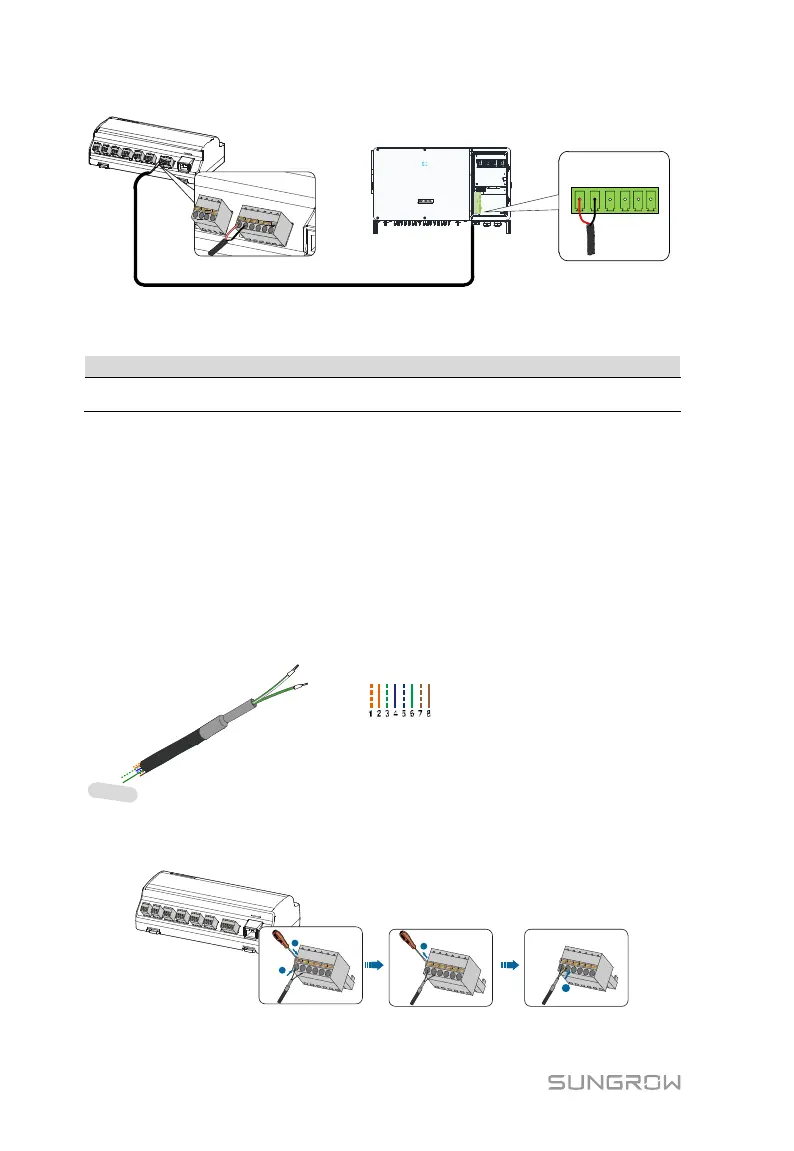
Logger1000
Inverter
A1 B1 PE A1 B1 PE
RS485
RJ45 port connection
Communication cable specification:
RS485 communication cable
Shielded twisted pair Ethernet cable
Cable connection procedure:
Step 1 Lead the RS485 communication cable from the inverter to the wiring area of
Logger1000.
Step 2 Strip the insulation layer of the communication cable with an Ethernet wire
stripper, and lead the corresponding RS485A/B signal cables out. Insert cord
end terminals into signal cable RS485+ A and signal cable RS485- B, and
crimp them with a crimper. Cut off the redundant signal cable and warp it
with a heat-shrink tubing.
Step 3 If the communication cable is Shielded Ethernet cable, white-green wire 3 is
defined as RS485- B wire and the green wire 6 as RS485+ A wire.
RS485+ A
RS485- B
1----8
Pin 3 and Pin 6 are used for
communication.
- Pin 3 to RS485- B
- Pin 6 to RS485+ A
Corresponding Relationship Between Cables
and Pins:
Pin 1: White-orange; Pin 2: Orange;
Pin 3: White-green; Pin 4: Blue;
Pin 5: White-blue; Pin 6: Green;
Pin 7: White-brown; Pin 8: Brown.
Step 4 Connect the communication cable to the RS485 ports of the Logger1000, as
shown in the figure below.
Step 5 Connect the Logger1000 to the inverter.