6
Solar-Storage-Charging Solution
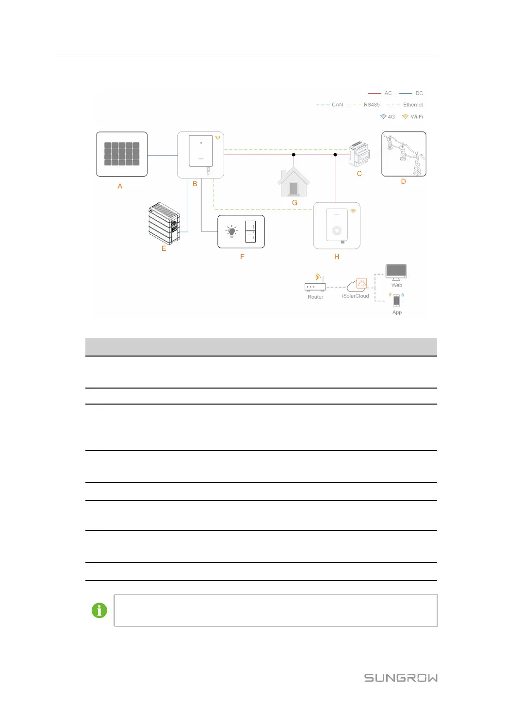
figure 1-4 System topology diagram of the solar-storage-charging solution
Position
Description
Note
A
PV strings
Compatible with monocrystalline silicon, polycrystal-
line silicon, and thin-film modules without grounding.
B Inverter SH5.0RT / SH6.0RT / SH8.0RT / SH10RT
C
Energy meter
A smart energy meter that monitors power usage
and helps to avoid power outages caused by peak
electricity during home charging.
D
Utility grid
TT, TN, TN-C-S, TN-S, TN-C. The type of grid
grounding system depends on local regulations.
E
Battery A Li-ion battery.
F
Backup loads
Protected house loads directly connected to the
inverter.
G Normal loads
Non-protected house loads. They will be discon-
nected in case of grid failure.
H
AC-Charger
AC011E-01
For SUNGROW's solar-storage-EV charging solution, please refer to the user
manual of related inverter. See "7.2 Additional Information".
1 Product Overview User Manual
 Loading...