2 Product Introduction User Manual
10
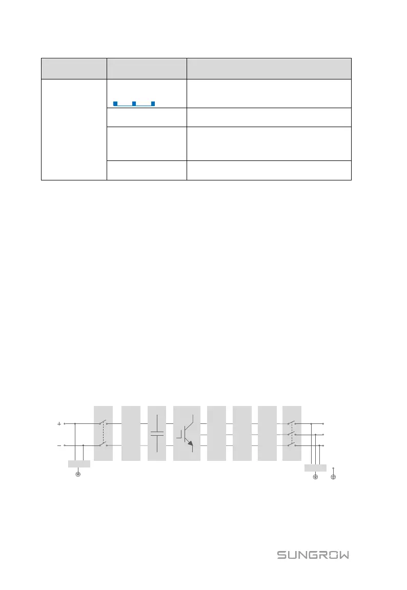
The DC or AC side is powered on and the
device is in standby or startup state (not
feeding power into the grid).
A fault occurs and the device cannot
connect to the grid
The Bluetooth communication is
connected and there is data
communication. Fault occurs.
Both the AC and DC sides are powered
down.
2.2.5 Battery Switch
Battery switch is designed for safely disconnecting the DC input current if
required.
The PCS works automatically when input and output meet the requirements.
Rotating battery switch to the “OFF” position will immediately cut off the flow of
DC current.
2.3 Technical Description
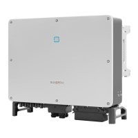
2.3.1 Principle Description
Inversion circuit converts DC power into AC power, which will be fed into the
utility grid via four core terminals. Protective circuits are designed to guarantee
PCS safe operation and human safety.
DC switch is integrated for safe disconnection of DC current. The PCS provides
standard interface RS485 for communication. PCS are also provided running
records display and parameters configuration via iSolarCloud APP.
L1
PE
L2
L3
AC SPD
Inverter Circuit
(DC/AC)
AC
Filter
AC
Relays
AC EMI
Filter
AC
Switch
DC
DC Switch
DC EMI
Filter
DC SPD
DC Bus
Fig. 2-4 Main Circuit Diagram