User Manual 2 Product Introduction
9
To disconnect the PCS from the AC output
safely
Second protective earth terminals as specified
in EN 50178.
Hang the PCS on the bracket.
Stop the PCS in emergency by pressing this
button down
To disconnect the PCS from the battery safely
Electrical connection
area
Includes DC terminal, AC terminal and
communication terminal.
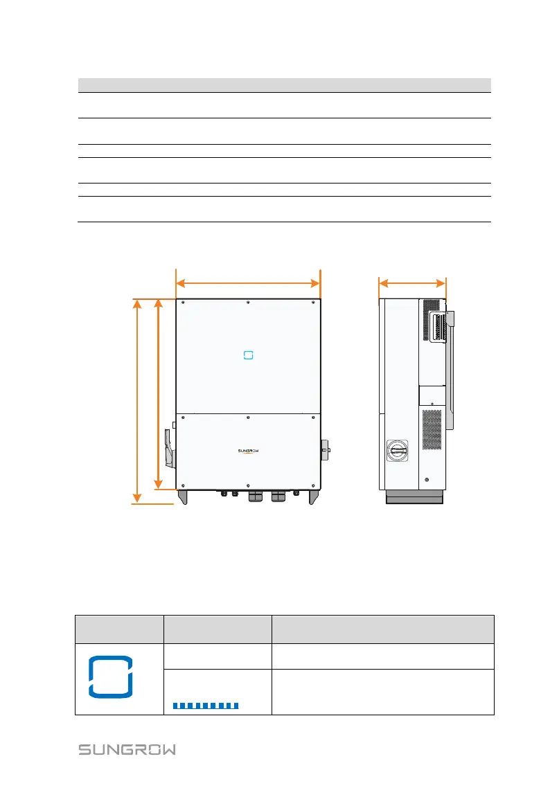
2.2.3 Dimensions of PCS
858mm/33.8in
600mm/23.6in
278mm/10.9in
800mm/31.5in
Fig. 2-3 Outline Dimensions of PCS
2.2.4 LED Indicator Panel
As an HMI, the LED indicator panel on the PCS front panel indicates the
present working state of the PCS.
Tab. 2-2 LED indicator description
The device is connected to the grid and
operating normally.
The Bluetooth communication is
connected and there is data
communication. No fault occurs.