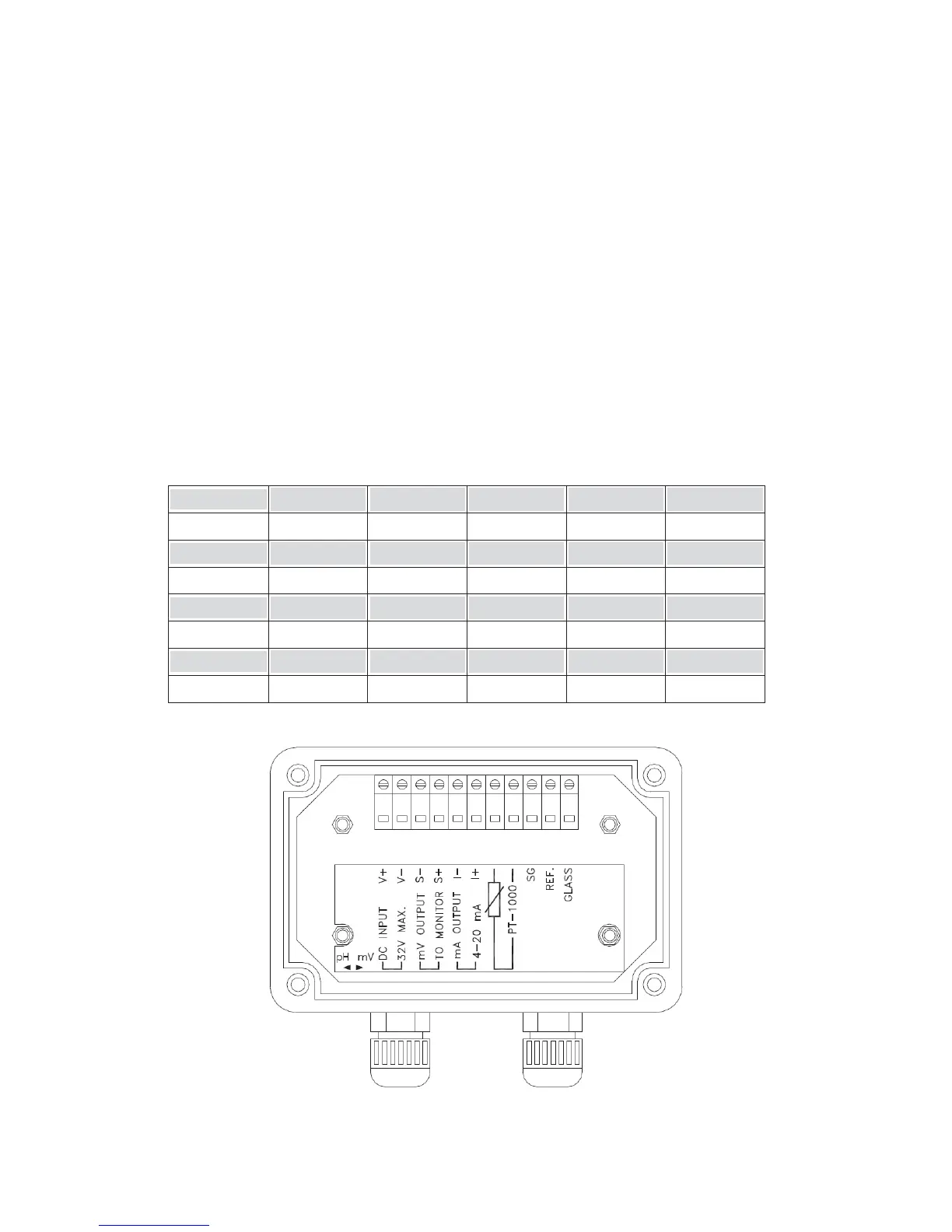
3.5 Connection of transmitter PC-3310 and accessorial transmitter PH-300T
A. Connect the GLASS point of transmitter PH-300T’s terminal to the electrode coaxial inner.
(Note: Remove the black conductive rubber); connect the REF point of transmitter PH-300T’s
terminal to the electrode coaxial shield.
B. See the two-wire distributing system and three-wire distributing system in the following page.
C. Sign “PT-1000” on transmitter PH-300T’s terminal is the connector for automatic temperature
compensation probe, PT-1000, or applies a fixed temperature compensation resistance.
D. The V+ and V- of transmitter PH-300T’s terminal respectively connect to DC12V+ and – of the
controller.
E. The S+ and S- on transmitter PH-300T’s terminal respectively connect to GLASS and REF of
the controller.
F. The I+ and I- on transmitter PH-300T’s terminal are output (4-20mA), which can connect to
devices that receive current signals. (Note: The current output signal of this transmitter is
not insulating, and thus do not directly connect with a PLC!)
Note: Refer to the following table for proper fixed temperature compensation resistance
Temperature
0ć5ć10ć15ć20ć
R value ȍ ȍ ȍ ȍ ȍ
Temperature
25ć30ć35ć40ć45ć
R value ȍ ȍ ȍ ȍ ȍ
Temperature
50ć55ć60ć65ć70ć
R value ȍ ȍ ȍ ȍ ȍ
Temperature
75ć80ć85ć90ć100ć
R value ȍ ȍ ȍ ȍ ȍ
км
 Loading...