Istruction Manual for Operation and Maintenance SPX-960:
To disassemble the side boom (Fig. 19) refer to section «4.7 Installation of boom and blocks».
- Side boom 28’ ............................................................................................................................ 2450 Kg
- N. 2 counterweight leaf packs: .................................................................................4670 Kg + 6670 Kg
- A-frame: ........................................................................................................................................ 550 Kg
- Steps .............................................................................................................................................. 32 Kg
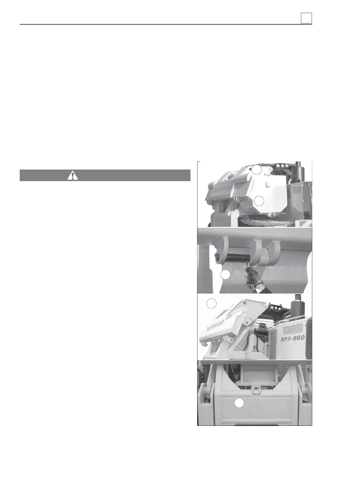
To disassemble the counterweight leaf packs (#1 at the front and #1 at the back) having a screw and pin
lock, undo the two large screws (1 in Fig. 18, front and back) and remove the two pins (2 in Fig. 18, front
and back).
Move the load-bearing frame as far out as to be able to lift one pack of leaves at a time easily and safe-
ly.
To disassemble the counterweight leaf packs (#1 at the front and #1 at the back) having a bolt lock, undo
the two bolts (3 in Fig. 18, front and back).
Move the load-bearing frame as far out as to be able to lift one pack of leaves at a time easily and safe-
ly.
WARNING
Transport the machine only after the counterweight has
been placed in vertical position and the frame has been
locked using the supplied safety bolt (4 in Fig. 18).
Before loading operations, make sure that the vehicle is
qualifi ed for this type of transportation and it has the correct
dimensions and capacity to bear the machine weight. This
information is also useful to check whether the machine can
be transported in narrow or low places.
The machine has a permanent integral hydrostatic drive and
cannot be towed with the engine off. To move the machine,
drive it from the control station.
The platform the machine is meant to be loaded onto must be
perfectly fl at. This will prevent the load from moving. Loading/
unloading ramps must not exceed a max. tilt of 15°.
• Check that the ground in the loading area is compact, fl at
and dry.
• Check that the ramps and support surfaces are not dama-
ged: they must not present weak points, missing edges or
excessive wear. If these surfaces prove unsafe, weak or
instable, do not load the machine. Make sure that the loa-
ding equipment and transport vehicle are in good condition
and have the proper capacity for loading operations.
• Engage the trailer brake and put blocks under the wheels
so as to stop it from moving. Align the ramps with the center
of both the trailer and the machine (Fig. 17).
• Make sure that both ramps are at the same height. The
max. tilt of the ramps must be 15°. Position the ramps so
that they coincide with the center of the tracks.
• Remove any mud from the undercarriage so that the ma-
chine does not slip sideways on the ramps. Also remove
any traces of water, snow, ice, grease, oil, etc. from the
ramps
3
Fig. 18 - Counterweight leaves
1) Counterweight leaf mounting screw - 2) Pins
- 3) Counterweight leaf mounting lock 4)
Counterweight without leaves 5) Safety bolt
4
5
3
1
2
3-4
MACHINE TRANSPORTATION