Istruction Manual for Operation and Maintenance SPX-960:
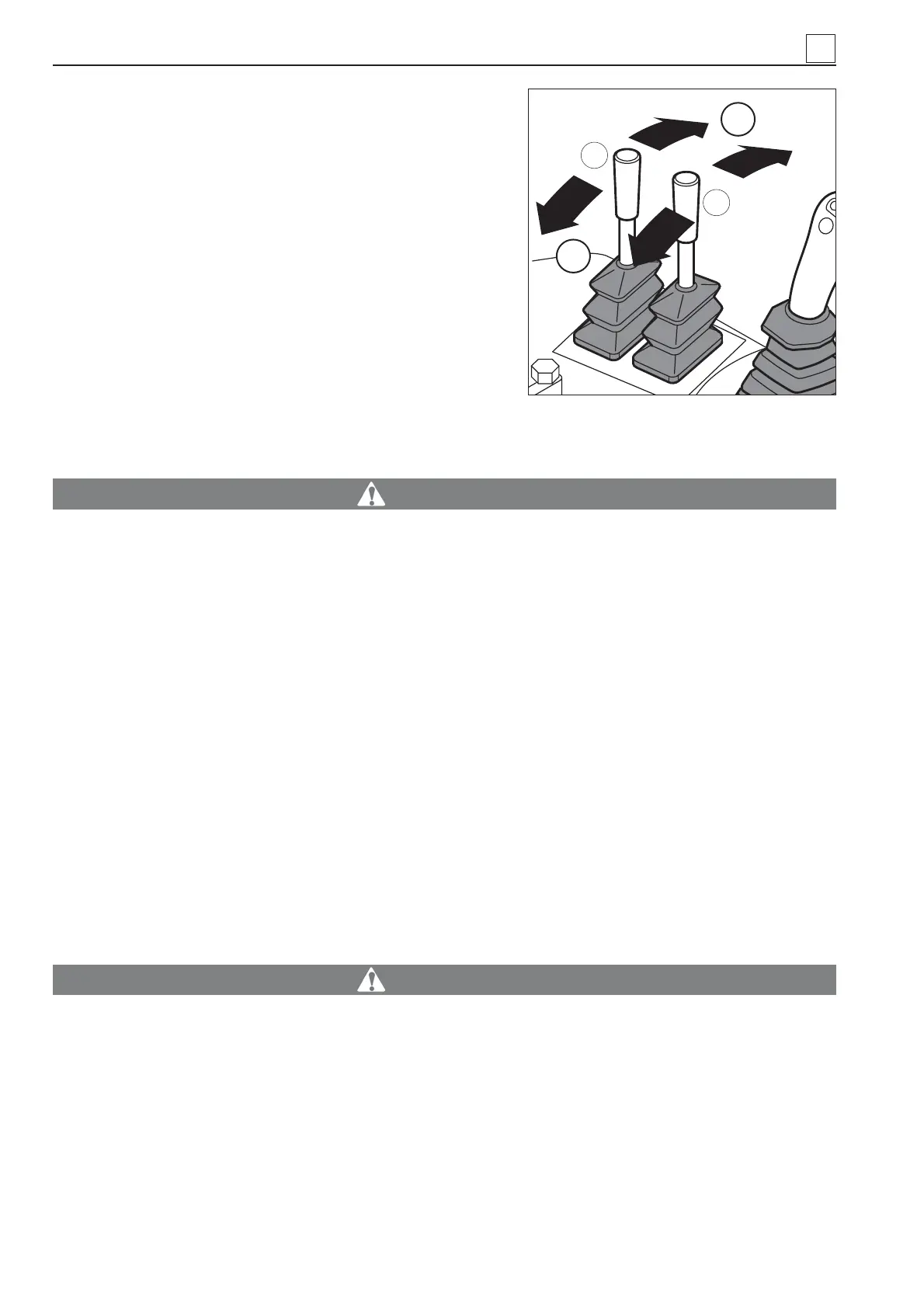
Levers 1 and 2 (Fig. 43) are used for fi ne steering corrections
of the track control.
- Push lever 1 to “A” to slightly let the machine turn right; pull
the lever to “B” to let the machine go to the initial position.
- Push lever 2 to “A” to slightly let the machine turn left; pull the
lever to “B” to let the machine go to the initial position
4.4.3 PIPE LAYER SHUT DOWN
Shut down the engine, and the pipe layer consequently, as
described below
WARNING
Whenever machine operation is stopped, no matter what the reason for the shutdown is, make
sure that all the controls are in the neutral position.
1) Turn the key of the master switch of the anti-tipping system (37 in Fig. 34) and remove it from its
lock.
2) Push the green decelerator button to cut out power to the engine (15 in Fig. 30) and let it run at min.
speed.
3) Turn the ignition key (6 in Fig. 28) anticlockwise and remove it from its lock.
4) Press the parking brake button (20 in Fig. 31): the light built in the button turns red.
5) Turn the key (Fig. 42) to position “A” to disable the battery and remove it from its lock.
6) Put the safety lever (Fig. 38) in position “A”.
- Before leaving the machine, if the machine is left unattended, collect the three keys for pipe layer ope-
ration and give them to the machine (or work site) supervisor.
WARNING
DO NOT LEAVE THE MACHINE UNATTENDED IF ENGINE IS RUNNING.
If the external temperature is below 0°C, and the radiator has not been fi lled with an antifreeze mix,
drain the water and fi ll it with a suitable antifreeze mix.
At temperatures below 5°C, the engine must be started very slowly for 10 minutes. At average
temperature, it must be started for 5 minutes so that it reaches approx. 25° to 30°.
When this start-up operation is performed, there must be no load hanging from the boom.
4
4-24
A
1
2
Fig. 43
B
MACHINE OPERATION