Istruction Manual for Operation and Maintenance SPX-960:
4.1 MACHINE SCOPE
The «Pipe Layer SPX 960» is a CE-marked machine in compliance with the requirements of European
Directive 98/37/EC (Machinery Directive) and Directive 2004/108/EC on electro-magnetic compatibility as
declared in the Declaration of Conformity which is released for every machine.
The «Pipe Layer SPX 960» is a slow gear earth moving machine that is powered by a diesel engine. It
moves on tracks that are controlled by hydraulic motors and is driven by an operator from the operator
control cabin (7 in Fig. 20).
This machine (PIPE LAYER) is supplied with lifting equipment and was exclusively designed to lift and
lay pipes on pipeline projects.
WARNING
All different uses of this machine from those described in this instruction manual relieve the Ma-
nufacturer from any and all responsibility for damage against persons, animals or property.
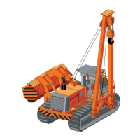
4.2 MACHINE DESCRIPTION
The machine consists of a tracked tractor whose frame features a side boom (16 in Fig. 20) including blocks
and a hook (14 in Fig. 20). The machine structure comprises a load-bearing framework. The framework
fi ts the right- and left-hand tracks, the engine compartment (25 in Fig. 20), the control cabin (9 in Fig. 20),
the counterweight rack (26 in Fig. 20) and the side boom.
Two winches control lifting and lowering of the boom (5 in Fig. 20) and lifting and lowering of the blocks
(14 in Fig. 20).
A hydraulic system, which is fully operated from the operator control cabin through the diesel engine,
controls all machine movements as well as lifting and lowering of the different parts.
The tracked carriage (21 & 24 in Fig. 20) enables the pipe layer to move forward. It is driven by hydraulic
motors that are operated by the levers installed in the operator cabin.
The machine and its operating functions are controlled from the control cabin (7 in Fig. 20) to which ac-
cess
is gained from a number of steps (19 in Fig. 20).
The control panel features the following buttons and levers: engine ignition, travel speed selection, equi-
pment movements and emergency stop. The operator uses the control panel to operate the machine and
monitor all the operating stages.
The winches are fi tted to engage and lift the boom and blocks. They consist of:
• an integrated planetary gearbox with rotary body and a triple gear in an oil bath, a negative multiple disk
brake with hydraulic opening that is controlled by a pilot valve controlling load lowering operations;
• a hydraulic axial piston motor with constant displacement – tilt cylinder block system;
• a high quality metal drum with a wire rope screwed-on plate stop.
4
4-3
MACHINE OPERATION