Istruction Manual for Operation and Maintenance SPX-960:
32) Fuse-holder blocks
33) Visio monitor (OPTIONAL).
34) Anti-tipping system bypass key
35) Anti-tipping system power switch
36) White light - anti-tipping electrical system error
37) Anti-tipping light alert depending on lifting capacity
41) Battery on/off key on engine hood left-hand side (A battery ON - B battery OFF)
43) Electronic control unit
45) Safety lever
46) PC plug for CPU
4.3.2 CONTROLS AND CONTROL DEVICES
Below is a description of the controls and control devices installed in the operator control station.
WARNING
It is essential to get familiar with the machine controls and
fi ne movements before starting operation.
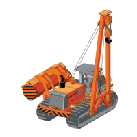
1) Left-hand drive lever (Fig. 22).
2) Right-hand drive lever (Fig. 22).
Levers 1) and 2) are used for fi ne steering corrections of
the track control.
LEVER 1 (Fig. 22):
- push lever 1 to “A”: the left-hand track moves forward
and causes the machine to turn right. When the lever is
released, it automatically goes back to neutral position;
- pull lever 1 to “B”: the left-hand track moves backward
and causes the machine to turn left. When the lever is
released, it automatically goes back to neutral position.
LEVER 2 (Fig. 22):
- push lever 2 to “A”: the right-hand track moves forward
and causes the machine to turn left. When the lever is
released, it automatically goes back to neutral position;
- pull lever 2 to “B”: the right-hand track moves backward
and causes the machine to turn right. When the lever is
released, it automatically goes back to neutral position.
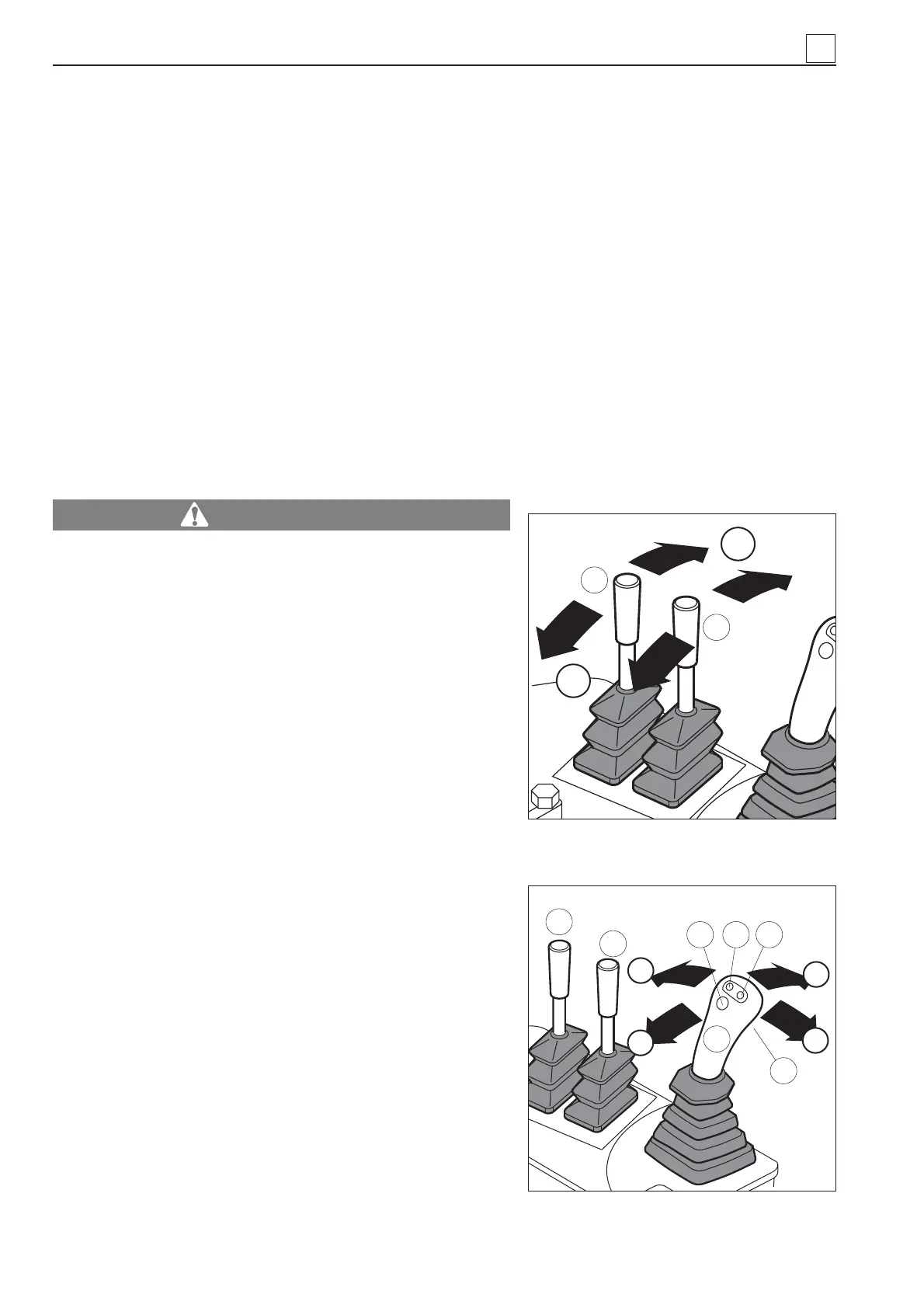
3) Multiple function joystick for drive control (Fig. 23). The
machine direction (i.e. back-forward, right-left and interme-
diate positions) and progressive speed are dependant on
the type of movement controlled by the joystick. The four
buttons built in the joystick are used to select the number
of engine rpm (preliminarily set).
- Push the joystick to “A” to let the pipe layer move for-
ward.
Fig. 23
1
2
C
A
B
E
7
654
3
A
1
2
Fig. 22
B
4
4-8
MACHINE OPERATION