Istruction Manual for Operation and Maintenance SPX-960:
5) Start the pipe layer up as instructed in section «4.4.1 Pipe
layer start-up».
6) Keep the boom lifted from the ground by approx. 1.5 to 2
meters. With the help of a hoist lift the two hook blocks
(connected) (6 in Fig. 47) slide the rope out from the two
boom frames. Put the articulated attachment (5 in Fig. 47)
in its housing and fi t the pin (4 in Fig. 47).
Secure the pin (4 in Fig. 47) with the supplied stop piece,
remove the bracket connecting the two blocks and put it in
its housing.
DANGER
In this case too the hook control winch is engaged ex-
clusively if the safety device bypass key (36 in Fig. 47) is
turned to position “ON”.
7) To disassemble the boom, repeat the operations above in
reverse sequence using the correct precautions.
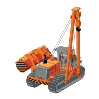
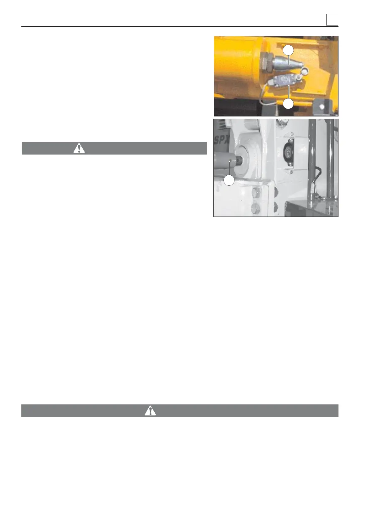
4.7.1 BOOM KICKOUT
Lift the boom to an almost vertical position: the system will automatically stop the boom travel.
When the boom reaches the almost vertical position, it engages a mechanical kickout device consisting
in a strut bar (1 in Fig. 48). The strut bar, on its turn, engages a micro switch (2 in Fig. 48) which starts a
solenoid valve that stops the boom from lifting.
The boom kickout is already set when the machine is released from the factory. If it needs calibration,
because it goes out of sync or for other reasons, set it from the strut bar.
How to set the book kickout Bring the boom to an almost vertical position at a one meter distance (ap-
prox.) from the external profi le of the track using the set screw (3 in Fig. 48) until the micro switch (2 in
Fig. 48) engages to stop the boom lift.
4.8 ANTI-TIPPING AND ANTI-TWO BLOCK CONTROL UNIT
The pipe layer is provided with a unit which controls the anti-tipping system and is located in the control
panel.
ATTENZIONE
The section below refers to a pipe layer featuring a standard power unit. For pipe layers fea-
turing an optional terminal, refer to section «4.3.4 Optional Visio terminal features». WHEN IN
DOUBT, CONTACT SCAIP AFTER-SALES SERVICE.
4
4-30
Fig. 48
1
2
3
MACHINE OPERATION