Chapter 1: Overview
1-5
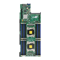
X10DRT-B+ Motherboard Jumpers
Jumper Description Default Setting
JBT1 Clear CMOS See Chapter 2
JPB1 Baseboard Management Controller (BMC)
Enable
Pins 1-2 (Enabled)
JPG1 VGA Enable Pins 1-2 (Enabled)
JPME2 Manufacturing Mode Pins 1-2 (Normal)
JWD1 Watch Dog Timer Enable Pins 1-2 (Reset)
JVRM1/2 I
2
C Bus for VRM Pins 1-2 (BMC: Normal)
X10DRT-B+ Motherboard Connectors
Connectors Description
Battery (JBAT1) Onboard CMOS battery (See more info in Chapter 3)
FAN3, FAN4 System fan headers
IPMI_LAN Dedicated IPMI LAN port
JF1 Power and front control panel connector
JF2 PCI-E 3.0 x4 slot supported by CPU1
JSD1 SATA DOM (Disk-On-Module) power connector
JTPM1 TPM (Trusted Platform Module)/Port 80 header
SIOM CPU1 PCI-E 3.0 x16 slot for proprietary add-on module use
SLOT1 PCI-E 3.0 x16 slot supported by CPU1
SLOT2 PCI-E 3.0 x16 slot supported by CPU2
S-SATA3 SATA DOM with power-pin connector
SXB1 PCI-E 3.0 x4 slot (supported by CPU1) and SATA connec-
tions (I-SATA0~5 & S-SATA0~2)
SXB2 PCI-E 3.0 x24 slot supported by CPU2
UID SW UID (Unit Identier) switch
USB0/1 (3.0) Back panel USB 3.0 ports
VGA Back panel VGA port