Chapter 2: Installation
2-35
LED4
A-SATA1
A-SATA0
I-SATA1
I-SATA0
I-SATA3
I-SATA2
JPUSB2
1
JPUSB1
1
JLED1
1
1
JPL1
1
JPME2
1
JPL2
1
JPAC1
1
1
JWD1
1
JVR1
1
JBT1
JSTBY1
1
JSD1
COM1
JF1
DESIGNED IN USA
C7Z97-OCE
REV:1.01
BIOS
LICENSE
FOR HOME OR OFFICE USE
With FCC Standards
Tested to Comply
JPW2
1
1
JL1
1
JL2
JWOR1
JSPDIF_OUT
1
JI2C1
1
JI2C2
1
JPW1
MAC CODE
BAR CODE
1
JITP1
2
LED1
SP1
JCHLED1
1
FAN3
1
FAN2
FAN5
1
FAN1
FAN4
1
1
JD1
JAUDIO1
POWER
BUTTON
(3.0)
A-SATA0A-SATA1
I-SATA4I-SATA5
I-SATA2I-SATA3
I-SATA0I-SATA1
CLEAR CMOS
1-2
ENABLE
JPUSB2:USB6/7 Wake Up
2-3
DISABLE
ENABLE
DISABLE
JPUSB1:USB0/1 Wake Up
2-3
1-2
(3.0)
USB 2/3
USB 12/13
USB 14/15(3.0)
CPU
CPU_SLOT2 PCI-E 3.0 X4 (IN X16)
PCH_SLOT1 PCI-E 2.0 X1 (INX4)
PCH_SLOT5 PCI-E 2.0 X1 (INX4)
PCH_SLOT3 PCI-E 2.0 X1 (INX4)
LAN2
LAN1
JWD1:
JBR1:
2-3:BIOS RECOVERY
1-2:NORMAL
JPME1:
2-3:ME RECOVERY
1-2:NORMAL
JSD1:
ENABLE
LAN2
DISABLE
2-3
1-2
JPL2
LAN1
DISABLE
ENABLE
2-3
1-2
JPL1
JWOR1:
2-3:NMI
1-2:RST
WATCH DOG
CPU
2-3:ME MANUFACTURING MODE
USB 0/1
1-2:NORMAL
JPME2:
SATA DOM PWR
JL1:
JLED1:
3 PIN POWER LED
AUDIO FP
HDD PWR
LEDLED
DIMMB1
DIMMB2
NIC1
SPEAKER:1-4
JD1:
BUZZER:3-4
JI2C1/JI2C2
ON:ENABLE
OFF:DISABLE
NIC2
HD AUDIO
WAKE ON RING
USB4/5
USB6/7
OH/FF
LED
X
CHASSIS INTRUSION
DIMMA1
DIMMA2
RST
PWR
JF1
ON
ALWAYS POPULATE BLUE SOCKET FIRST
UNB NON-ECC DDR3 DIMM REQUIRED
CPU_SLOT4 PCI-E 3.0 X8 (IN X16)
CPU_SLOT6 PCI-E 3.0 X16
VGA/DVI
2-3:DISABLE
1-2:ENABLE
JPAC1:AUDIO
JPME1
OC1
OC2
OC3
HOME
HDMI/DP
1
MEMORY OC
JVR2
PS2
OC FRONT PANEL
JBR1
M
JBT1
BIOS RESTORE
USB6_charger
CLEAR CMOS
PCI-E M.2
CONNECTOR
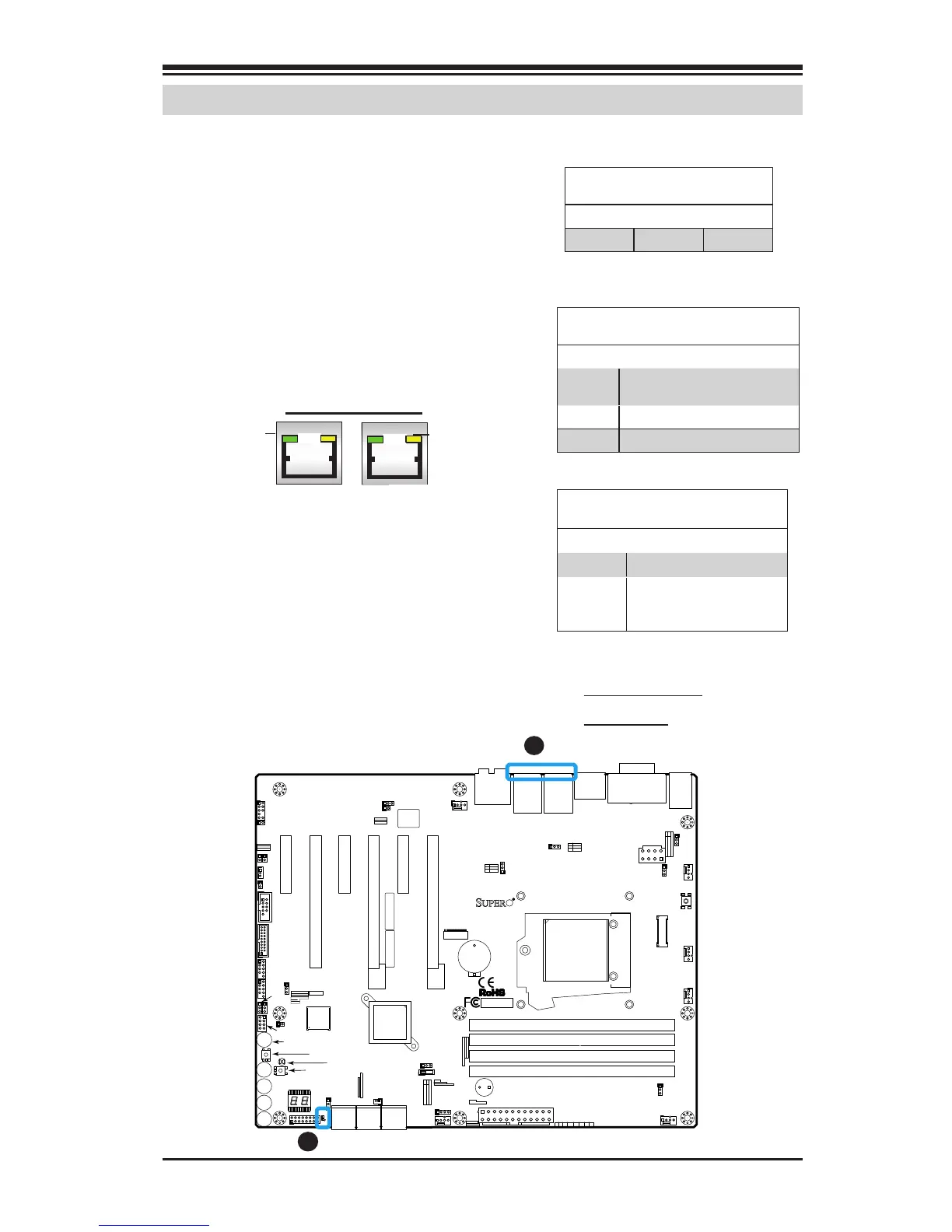
A. LAN 1/2 LEDs
B. PWR LED
A
B
LAN 1/LAN 2 LEDs
Two LAN ports (LAN 1/LAN 2) are located
on the I/O backplane of the mother-
board. Each Ethernet LAN port has two
LEDs. The yellow LED indicates activity,
while the Link LED may be green, am-
ber, or off to indicate the speed of the
connections. See the tables at right for
more information.
2-9 Onboard Indicators
LAN1 LAN2
Activity LED
Link LED
Onboard PWR LED Indicator
LED Status
Status Denition
Off System Off
On System on, or
System off and PWR
Cable Connected
Onboard Power LED (LED1)
An Onboard Power LED is located at
LED1 on the motherboard. When LED1
is on, the AC power cable is connected.
Make sure to disconnect the power cable
before removing or installing any compo-
nent. See the layout below for the LED
location.
GLAN Ports 1/2 Link Indicator
LED Settings
LED Color Denition
Off No Connection/10 Mbps/100
Mbps
Amber 1 Gbps
Green 10 Gbps.
GLAN 1/2 Activity Indicator
LED Settings
Color Status Denition
Yellow Flashing Active