2-12
Supermicro C7Z97-OCE Motherboard User’s Manual
LED4
A-SATA1
A-SATA0
I-SATA1
I-SATA0
I-SATA3
I-SATA2
JPUSB2
1
JPUSB1
1
JLED1
1
1
JPL1
1
JPME2
1
JPL2
1
JPAC1
1
1
JWD1
1
JVR1
1
JBT1
JSTBY1
1
JSD1
COM1
JF1
DESIGNED IN USA
C7Z97-OCE
REV:1.01
BIOS
LICENSE
FOR HOME OR OFFICE USE
With FCC Standards
Tested to Comply
JPW2
1
1
JL1
1
JL2
JWOR1
JSPDIF_OUT
1
JI2C1
1
JI2C2
1
JPW1
MAC CODE
BAR CODE
1
JITP1
2
LED1
SP1
JCHLED1
1
FAN3
1
FAN2
FAN5
1
FAN1
FAN4
1
1
JD1
JAUDIO1
POWER
BUTTON
(3.0)
A-SATA0A-SATA1
I-SATA4I-SATA5
I-SATA2I-SATA3
I-SATA0I-SATA1
CLEAR CMOS
1-2
ENABLE
JPUSB2:USB6/7 Wake Up
2-3
DISABLE
ENABLE
DISABLE
JPUSB1:USB0/1 Wake Up
2-3
1-2
(3.0)
USB 2/3
USB 12/13
USB 14/15(3.0)
CPU
CPU_SLOT2 PCI-E 3.0 X4 (IN X16)
PCH_SLOT1 PCI-E 2.0 X1 (INX4)
PCH_SLOT5 PCI-E 2.0 X1 (INX4)
PCH_SLOT3 PCI-E 2.0 X1 (INX4)
LAN2
LAN1
JWD1:
JBR1:
2-3:BIOS RECOVERY
1-2:NORMAL
JPME1:
2-3:ME RECOVERY
1-2:NORMAL
JSD1:
ENABLE
LAN2
DISABLE
2-3
1-2
JPL2
LAN1
DISABLE
ENABLE
2-3
1-2
JPL1
JWOR1:
2-3:NMI
1-2:RST
WATCH DOG
CPU
2-3:ME MANUFACTURING MODE
USB 0/1
1-2:NORMAL
JPME2:
SATA DOM PWR
JL1:
JLED1:
3 PIN POWER LED
AUDIO FP
HDD PWR
LEDLED
DIMMB1
DIMMB2
NIC1
SPEAKER:1-4
JD1:
BUZZER:3-4
JI2C1/JI2C2
ON:ENABLE
OFF:DISABLE
NIC2
HD AUDIO
WAKE ON RING
USB4/5
USB6/7
OH/FF
LED
X
CHASSIS INTRUSION
DIMMA1
DIMMA2
RST
PWR
JF1
ON
ALWAYS POPULATE BLUE SOCKET FIRST
UNB NON-ECC DDR3 DIMM REQUIRED
CPU_SLOT4 PCI-E 3.0 X8 (IN X16)
CPU_SLOT6 PCI-E 3.0 X16
VGA/DVI
2-3:DISABLE
1-2:ENABLE
JPAC1:AUDIO
JPME1
OC1
OC2
OC3
HOME
HDMI/DP
1
MEMORY OC
JVR2
PS2
OC FRONT PANEL
JBR1
M
JBT1
BIOS RESTORE
USB6_charger
CLEAR CMOS
PCI-E M.2
CONNECTOR
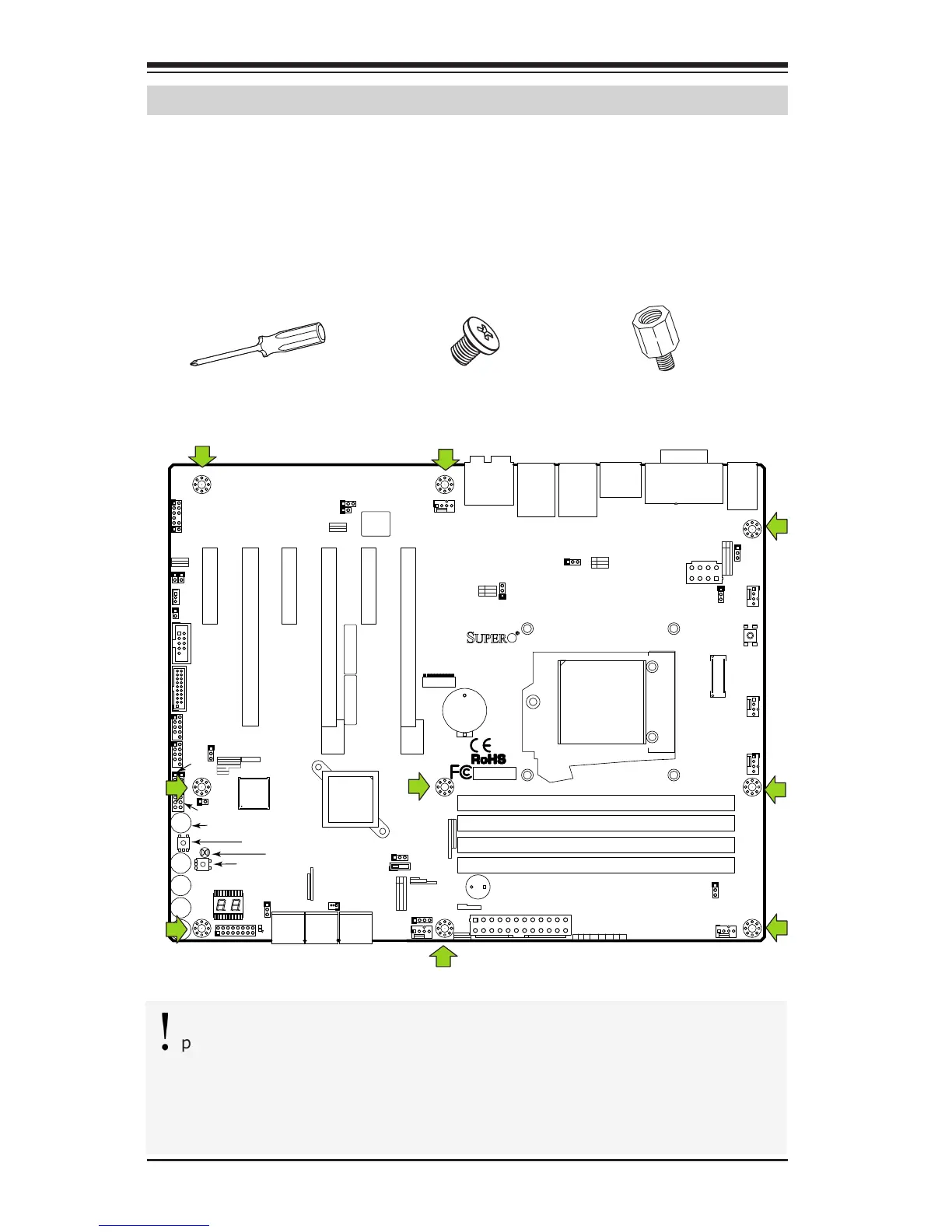
Location of Mounting Holes
Attention! 1) To avoid damaging the motherboard and its com-
ponents, please do not use a force greater than 8 lb/inch on each
mounting screw during motherboard installation. 2) Some compo-
nents are very close to the mounting holes. Please take precautionary
measures to avoid damaging these components when installing the
motherboard to the chassis.
2-5 Motherboard Installation
All motherboards have standard mounting holes to t different types of
chassis. Make sure that the locations of all the mounting holes for both
motherboard and chassis match. Although a chassis may have both plas-
tic and metal mounting fasteners, metal ones are highly recommended
because they ground the motherboard to the chassis. Make sure that the
metal standoffs click in or are screwed in tightly. Then use a screwdriver
to secure the motherboard onto the motherboard tray.
Philips Screwdriver
(1)
Standoffs (9)
Only if Needed
Philips Screws (9)
Tools Needed

 Loading...


