Chapter 2: Installation
2-9
LED4
A-SATA1
A-SATA0
I-SATA1
I-SATA0
I-SATA3
I-SATA2
JPUSB2
1
JPUSB1
1
JLED1
1
1
JPL1
1
JPME2
1
JPL2
1
JPAC1
1
1
JWD1
1
JVR1
1
JBT1
JSTBY1
1
JSD1
COM1
JF1
DESIGNED IN USA
C7Z97-OCE
REV:1.01
BIOS
LICENSE
FOR HOME OR OFFICE USE
With FCC Standards
Tested to Comply
JPW2
1
1
JL1
1
JL2
JWOR1
JSPDIF_OUT
1
JI2C1
1
JI2C2
1
JPW1
MAC CODE
BAR CODE
1
JITP1
2
LED1
SP1
JCHLED1
1
FAN3
1
FAN2
FAN5
1
FAN1
FAN4
1
1
JD1
JAUDIO1
POWER
BUTTON
(3.0)
A-SATA0A-SATA1
I-SATA4I-SATA5
I-SATA2I-SATA3
I-SATA0I-SATA1
CLEAR CMOS
1-2
ENABLE
JPUSB2:USB6/7 Wake Up
2-3
DISABLE
ENABLE
DISABLE
JPUSB1:USB0/1 Wake Up
2-3
1-2
(3.0)
USB 2/3
USB 12/13
USB 14/15(3.0)
CPU
CPU_SLOT2 PCI-E 3.0 X4 (IN X16)
PCH_SLOT1 PCI-E 2.0 X1 (INX4)
PCH_SLOT5 PCI-E 2.0 X1 (INX4)
PCH_SLOT3 PCI-E 2.0 X1 (INX4)
LAN2
LAN1
JWD1:
JBR1:
2-3:BIOS RECOVERY
1-2:NORMAL
JPME1:
2-3:ME RECOVERY
1-2:NORMAL
JSD1:
ENABLE
LAN2
DISABLE
2-3
1-2
JPL2
LAN1
DISABLE
ENABLE
2-3
1-2
JPL1
JWOR1:
2-3:NMI
1-2:RST
WATCH DOG
CPU
2-3:ME MANUFACTURING MODE
USB 0/1
1-2:NORMAL
JPME2:
SATA DOM PWR
JL1:
JLED1:
3 PIN POWER LED
AUDIO FP
HDD PWR
LEDLED
DIMMB1
DIMMB2
NIC1
SPEAKER:1-4
JD1:
BUZZER:3-4
JI2C1/JI2C2
ON:ENABLE
OFF:DISABLE
NIC2
HD AUDIO
WAKE ON RING
USB4/5
USB6/7
OH/FF
LED
X
CHASSIS INTRUSION
DIMMA1
DIMMA2
RST
PWR
JF1
ON
ALWAYS POPULATE BLUE SOCKET FIRST
UNB NON-ECC DDR3 DIMM REQUIRED
CPU_SLOT4 PCI-E 3.0 X8 (IN X16)
CPU_SLOT6 PCI-E 3.0 X16
VGA/DVI
2-3:DISABLE
1-2:ENABLE
JPAC1:AUDIO
JPME1
OC1
OC2
OC3
HOME
HDMI/DP
1
MEMORY OC
JVR2
PS2
OC FRONT PANEL
JBR1
M
JBT1
BIOS RESTORE
USB6_charger
CLEAR CMOS
PCI-E M.2
CONNECTOR
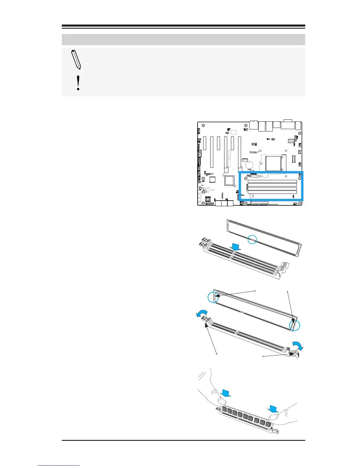
2-4 Installing DDR3 Memory
Note: Check the Supermicro website for recommended memory
modules.
Attention! Exercise extreme care when installing or removing
DIMM modules to prevent any possible damage.
DIMM Installation
1. Insert the desired number of
DIMMs into the memory slots,
starting with DIMMA2 (see the
next page for the location). For
the system to work properly,
please use the memory modules
of the same type and speed in
the same motherboard.
Release Tabs
Notches
2. Push the release tabs outwards
on both ends of the DIMM slot
to unlock it.
Press both notches
straight down into
the memory slot.
3. Align the key of the DIMM mod-
ule with the receptive point on the
memory slot.
4. Align the notches on both ends of
the module against the receptive
points on the ends of the slot.
5. Use two thumbs together to press
the notches on both ends of the
module straight down into the slot
until the module snaps into place.
6. Press the release tabs to the lock
positions to secure the DIMM mod-
ule into the slot.
Removing Memory Modules
Reverse the steps above to remove the
DIMM modules from the motherboard.

 Loading...


