1-10
Supermicro C7Z97-OCE Motherboard User’s Manual
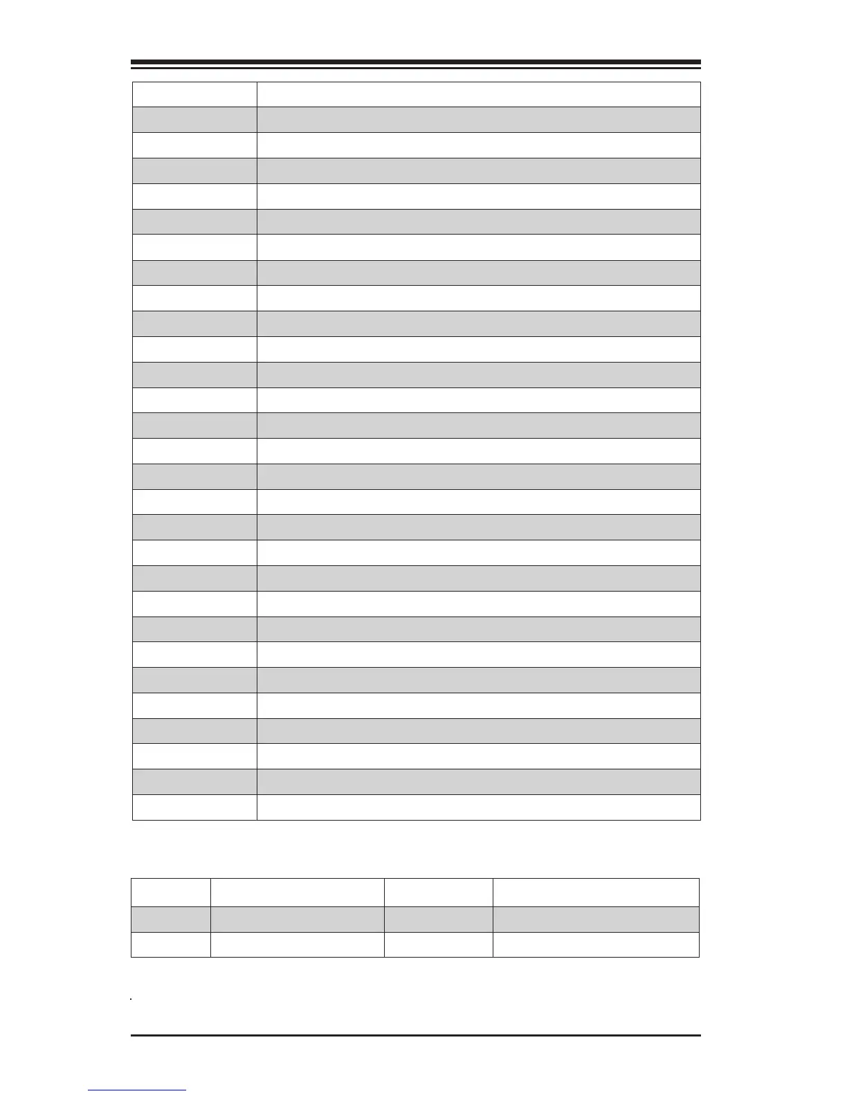
Connector Description
I/O Back Panel See Chapter 2-6
Audio FP Front Panel Audio Header
Battery Onboard Battery
COM1 COM1 Port Header
Fan 1,2,3,4,5 System/CPU Fan Headers (Fan1: CPU Fan)
JD1 Speaker/buzzer (Pins 1~4: External Speaker, Pins 3~4: Buzzer)
JF1 Front Panel Control Header
JL1 Chassis Intrusion Header
JLED1 Power LED Indicator Header
JPW1 24-pin ATX Main Power Connector (Required)
JPW2 +12V 4-pin CPU power Connector (Required)
JSD1 SATA DOM (Disk On Module) Power Connector
JSPDIF_OUT Sony/Philips Digital Interface (S/PDIF) Out Header
JSTBY1 Standby Power Header
SP1 Internal Speaker/Buzzer
A-SATA0/1 (ASMedia) Serial ATA (SATA 3.0) Port 0/1 (6Gb/sec)
I-SATA0~3 (Intel Z97) Serial ATA (SATA 3.0) Ports 0~3 (6Gb/sec)
USB 0/1 + PS2 Back Panel Accessible USB 2.0 Ports 0/1, PS/2 Mouse/Keyboard
USB 2/3, 12/13 Back Panel Accessible USB 3.0 Ports 2/3, 12/13
USB 4/5, 6/7 Front Panel Accessible USB 2.0 Headers 4/5, 6/7
USB 14/15 (3.0) Front Panel Accessible USB 3.0 Header 14/15
JCHLED1 Chassis LED Control (Supermicro Chassis only)
POWERBUTTON On Board Power Button
BIOS RESTORE Restores the BIOS from Firmware ('SUPER.ROM') in a USB memory device
OC1, OC2, OC3 Over-Clocking Buttons OC1(15%), OC2(20-25%), OC3 (User-Dened in BIOS)
PCI-E M.2 PCI-E M.2 Expansion Slot for M.2-compliant expansion cards
HOME (Below OC3 button) Default setting (non-OC)
OC FRONT PANEL Header for the Overclocking Panel (Optional, see 2-38 for installation details)
LED Description Color/State Status
LED1 Onboard Standby PWR LED Green: Solid on Power On
LED4 Status Display Digital Readout Download the status codes below*
*Download the AMI status codes at http://www.ami.com/support/doc/ami_aptio_4.x_status_codes_pub.pdf